There are many different extraction methods available in the
NPart object. They can be combined. By default,
none of these methods is enabled. But before enabling any of these
methods, it is recommended adjust the method's settings first to avoid
issues performance and memory footprint. See the following sections
for a description of the various settings.
Enabling an extraction method with the graphical user interface
is done by activating the "extract" check box, which is found on each
sub-page of the "Extract" page in the NPart editor.
In the Python environment, the same is achieved by setting the
"extract" property of the corresponding sub-object to the value
True. Example:
p.sfvbc.extract = True
p.cut.extract = True
![[Note]](common/images/admon/note.png) |
Note |
|---|---|
|
This extraction method is rarely used with structured Finite-Volume meshes. |
Extraction of whole elements is typically used for
-
Beam and shell Finite-Element models.
-
Post-processing of unstructured Finite-Volume meshes, where only (a part of) the surface mesh should be extracted.
-
1D- and 2D-models.
baspl++ does make some simplifications regarding the extraction and the display of various elements: Volume elements (tetrahedrons, pyramids, prisms/wedges, and hexahedrons) are extracted and displayed by extracting and displaying each of their faces. baspl++ cannot display volume primitives per se, but has to approximate them by surfaces. Shell elements are represented by their mid-surface. Beam elements are displayed as lines.
In the editor, the settings for element extraction are located on the "Elements" page. The "elements" method is enabled by activating the "extract" check box on that page. In Python, element extraction is enabled
p.elements.extract = True
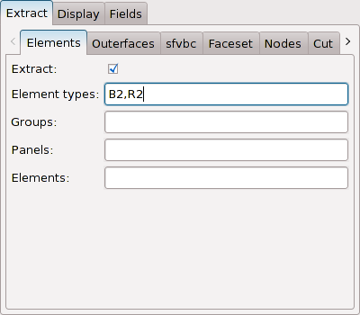
The following figure displays the Finite-Element mesh of a bridge model. This mesh consists of shell, beam, and cable elements. To the left, all elements are extracted. To the right, only the beam and cable elements are extracted.

The settings corresponding to the right part of the above figure are displayed in the following figure:
Most Finite-Element meshes contain elements of various types. Unstructured Finite-Volume meshes often contain surface elements as well as volume elements. The former may be triangles or quadrilaterals, while the latter may be tetrahedrons, pyramids, prisms, and hexahedrons).
In baspl++, element types are identified by their names. These names are defined in the database and must follow certain conventions, which are briefly explained. The element names begins with the prefix, possibly followed by one or more sub-strings, separated by period (".") characters. For instance,
Q4.S.MITC
means a four node quadrilateral ("Q4") stress-analysis ("S") element of the "MITC" (mixed-interpolation of tensorial components) type. baspl++ only considers the prefix. Thus, for baspl++, this element type is a four node quadrilateral surface element, while actually, being a shell element, the Q4.S.MITC element occupies a volume in 3D.
Among the prefixes being known to baspl++, the following are mentioned here:
-
P: Point elements. -
CMASS: Concentrated mass elements (for Finite-Element meshes). -
LandL2,RandR2,CandC2,BandB2: Line, rod, cable, and beam elements having two nodes. -
TandT3: Three node triangular elements. -
T6: Six node, second-order triangular elements. -
QandQ4: Four node quadrilateral elements. -
Q8andQ9: Eight/Nine node, second-order quadrilateral elements. -
TE10: Ten node tetrahedral second-order elements. -
PY: Five node pyramidal elements. -
PRandPR6: Six node prismatic elements. -
PR15: Fifteen node prismatic, second-order elements. -
HE20andHE27: Second-order hexahedral elements with 20 and 27 nodes, respectively.
For unstructured Finite-Volume meshes, only the "T", "Q", "TE", "PY", "PR", and "HE" element types are defined usually.
The "etypes" property accepts a string consisting of a comma-separated list of element names. For instance:
p.elements.etypes = 'T3.S.MITC,Q4.S.MITC'
will restrict the extraction to the element types T3.S.MITC and Q4.S.MITC. By default, this property is empty, meaning that no restriction is applied. In the graphical user interface, the same string is entered (but without the quotes).
To extract all surface elements of an unstructured Finite-Volume mesh:
p.elements.etypes = 'T,Q'
It is possible to specify element types that are actually not defined for the given mesh. This will not produce any error; instead, these element types will just never be matched by any element.
Unstructured Finite-Volume meshes and b2000 Finite-Element meshes may have group (and panel) numbers defined for the elements or a subset thereof. For instance, in a Finite-Volume mesh, elements of the wall surface, of the symmetry plane, of the far field, etc. may have different group numbers.
The "groups" and "panel" properties allow for restricting the extraction to ranges of group and panel numbers. They accept a comma-separated list of numbers and intervals. For instance,
p.elements.groups='1,3-4,6'
will restrict the elements extraction to those elements having group numbers of either 1, 3, 4, or 6.
Elements belonging to a group (for instance, the wing surface) may be partitioned into panels (the CAD surface patches). These panels are identified by numbers. The "panel" property works in the same way as the "group" property does.
It is possible to specify group or panel numbers that are actually not defined for the given mesh. This will not produce any error; instead, these numbers will just never be matched by any element.
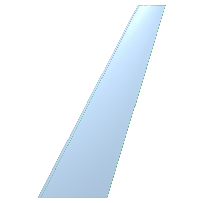
The following figure displays the surface of a fixed wing extracted by means of element group numbers:
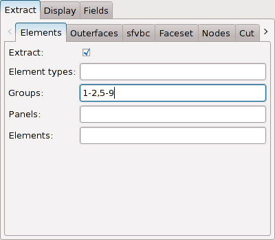
The corresponding settings in the NPart
editor are displayed in the next figure. The group number 3 defines
the far field, while group number 4 defines the symmetry
plane.
In a Model in
baspl++, elements (and nodes) are grouped
in branches. Branches are identified by numbers. Inside a branch,
elements and nodes are again identified by numbers. These numbers
are unique, but not necessarily contiguous.
The element extraction (as well as many of the other extraction methods) can be restricted to ranges of branch- and element numbers, for instance
p.elements.elements = '1'
will restrict the extraction to the elements of branch 1. In the graphical user interface, this is entered into the entry widget without the quotes.
The "elements" property accepts a comma-separated list of branch/element numbers or intervals thereof. The branch and element numbers are separated by colon (":") characters. This is illustrated by the following examples:
-
'1,3-7': Restrict to elements having a branch number of either 1, 3, 4, 5, 6, or 7.
-
'1:1-1:100': Restrict to elements having a branch number of 1 and an element number between 1-100.
-
'1,2:40-2:45': Restrict to elements either having a branch number of 1 and any element number, or having a branch number of 2 and an element number between 40-45.
During extraction, the branch and element number of each element are tested against the "elements" property, and only elements matching the criterion are extracted. Hence, the criterion may contain branch and/or element numbers that are not present in the mesh. In such cases, these numbers will not be matched by any element.
For meshes containing many volume elements, it is often useful
to extract only the faces of those elements that are visible from
the outside. This is done with the outerfaces
sub-object. In the editor, the settings can be found on the
"Outerfaces" page. In Python, the method is enabled
p.outerfaces.extract = True
The following figure displays the outer surface of the Finite-Element mesh of a bolt.

The next figure shows the corresponding settings in the
NPart editor:

The extraction of outer faces can be restricted to ranges of branch- and element numbers, for instance
p.outerfaces.elements = '1'
will restrict the extraction to the elements of branch 1. Refer to Section 3.2.4 for more information.
|
Note |
|---|---|
|
This extraction method is not used with Finite-Element meshes. |
Databases containing structured Finite-Volume (SFV) meshes for use with the NSMB flow solver define surfaces (far field, symmetry planes, wall, etc.). The "sfvbc" method can extract these surfaces.
In the graphical user-interface, this method is enabled by
activating the "extract" check box on the
Extract->sfvbc page of the
NPart editor. In the Python environment, assuming
that the variable "p" references the NPart
object, this is done with
p.sfvbc.extract = True
The following figure displays the wall surface of the half-model of a wing-body configuration:

The following figure displays a screenshot of the
NPart editor with the corresponding
settings:

These surfaces are defined by assigning boundary condition numbers (bc) to so-called windows defined on the block's surfaces. These numbers are stored on the database. baspl++ can extract faces in function of their boundary condition number. For NSMB, the meaning of some typically-used boundary condition number ranges is listed here (for more precise information, consult the NSMB user guide):
-
130-150: Various far-field conditions.
-
300-399: Wall surface.
-
412 and 413: Symmetry planes.
The bc property defines the boundary
condition numbers for which faces will be extracted from the mesh.
By default, it contains the range 300-399, thus selecting the wall
surface. It is a comma-separated list of integer ranges. The
following example sets extracts the wall surface and the
symmetry-plane with the normal in y-direction.
p.sfvbc.bc = '300-399,412'
If the list is empty, e.g.
p.sfvbc.bc = ''
or
p.sfvbc.bc = None
no restriction is applied and all surfaces will be extracted.
The extraction can be further restricted to ranges of branch- and element numbers, for instance
p.sfvbc.elements = '1-4,5:40-5:60'
will restrict the extraction to all elements of branches 1 to 5, and to the elements 40-60 of branch 5. Refer to Section 3.2.4 for more information.
|
Note |
|---|---|
|
This extraction method is not used with Finite-Element or structured Finite-Volume meshes. |
For unstructured Finite-Volume meshes, there is the
possibility to extract faces that are marked in dedicated datasets
called SELELF. Such a dataset contains a set of
tuples (element-number, face-number, flag). The "faceset" sub-object
extracts element faces according to the contents of the
SELELF datasets.
p.faceset.extract = True
The following figure displays the extracted wall surface (including element the edges) of the half-model of a re-entry vehicle:

The corresponding settings are displayed below:

Often, the SELELF datasets are enumerated
with a non-zero CYCLE enumerator. In this case,
the cycle property must be set accordingly:
p.faceset.cycle = 1
The
flag property permits to restrict the selection
to those faces matching the flag. The default value 0 will match any
face. Example:
p.faceset.flag = 4
The extraction can be restricted to ranges of branch- and element numbers, for instance
p.faceset.elements = '1:1-1:100'
will restrict the extraction to the elements 1-100 of branch 1. Refer to Section 3.2.4 for more information.
The extraction methods described above extract elements (or element faces). These are, according to their type, then displayed. The nodes themselves will not be displayed. To extract and display nodes (as points), the "nodes" extraction method has to be used.
In the graphical user interface, in the
NPart editor, go to the
Extract->Nodes page and activate the "extract"
check box. In the Python environment, assuming that the variable "p"
references the NPart object, this is done with:
p.nodes.extract = True
baspl++ is capable of displaying several millions of nodes without much problems, thus, the "nodes" extraction method can be used without making any restriction on the nodes to be extracted.
In the following figure, the nodes of an unstructured Finite-Volume mesh are displayed. The right part also shows the wall surface.

The next figure shows the corresponding settings in the
NPart editor:

In a Model in
baspl++, elements and nodes are grouped
in branches. Branches are identified by numbers. Inside a branch,
elements and nodes are again identified by numbers. These numbers
are unique, but not necessarily contiguous.
The nodes extraction can be restricted to ranges of branch- and node numbers, for instance
p.nodes.nodes = '1'
will restrict the extraction to the nodes of branch 1. In the graphical user interface, this is entered into the entry widget without the quotes.
The "nodes" property accepts a comma-separated list of branch/nodes numbers or intervals thereof. The branch and element numbers are separated by colon (":") characters. This is illustrated by the following examples:
-
'1,3-7': Restrict to nodes having a branch number of either 1, 3, 4, 5, 6, or 7.
-
'1:1-1:100': Restrict to nodes having a branch number of 1 and an element number between 1-100.
-
'1,2:40-2:45': Restrict to nodes either having a branch number of 1 and any nodes number, or having a branch number of 2 and an nodes number between 40-45.
During extraction, the branch and nodes number of each node are tested against the "nodes" property, and only nodes matching the criterion are extracted. Hence, the criterion may contain branch and/or nodes numbers that are not present in the mesh. In such cases, these numbers will not be matched by any node.
When dealing with volume meshes, cutting the volume into a slice, and thus creating a surface that can be displayed, is a convenient form of data reduction. To this end, the "cut" sub-object is being used.
p.cut.extract = True
The "cut" method is a model reduction method. The intersection
-
of volume elements with the cutting plane yields surface elements (faces),
-
of surface elements with the cutting plane yields line (or wire) elements,
-
of line elements with the cutting plane yields point elements.
This is illustrated in the following figure: The left part shows the cut elements as faces, lines, and points, while the right part of the figure also displays the edges of the faces. In both cases, the wall surface is also displayed.

The cutting plane is defined via a point inside the cutting plane, the "point" property, and the plane's normal vector, the "normal" property:
p.cut.point = [10, 0, 0]
p.cut.normal = [1, 0, 0]
The values for the "point" and the "normal" properties can be entered as numbers and also can be modified using the sliders. For the "point" property, the slider ranges encompass the mesh's bounding box. For the "normal" property, the slider's ranges go from -1 to +1.

The extraction can be restricted topologically by means of the "restrict" property. The following options are available:
-
elements: Only cut those elements selected by the "elements" method. -
outerfaces: Do not cut volume or line elements. Only cut faces that have no matching neighbour. Any restriction put on the "outerfaces" method also apply here. -
sfvbc: Do not cut volume or line elements. Only cut faces selected by the "sfvbc" method. For use with structured-block Finite-Volume meshes. -
facesetDo not cut volume or line elements. Only cut faces selected by the "faceset" method. For use with unstructured Finite-Volume meshes. -
ijkDo not cut volume or line elements. Only cut faces selected by the "ijk" method. For use with structured-block Finite-Volume meshes.
These options make it possible for instance to cut surface(s) only, instead of cutting the volume. It is not necessary (but nevertheless possible) to enable the extraction of any of these methods; the "cut" method simply makes use of their respective settings.
Note that the extraction cannot be restricted to the "isosurface" method (this would result in iso-lines). Instead make an unrestricted cut, do not display element faces, and activate the the "isoline" method.
The extraction can be geometrically restricted using the "box" property. The box's centre is located at the cutting plane's "point". Only elements being (partially or fully) inside the box will be intersected.
This feature is useful when more than a single cutting plane is needed. The cutting planes are parallel (the "normal" property is the same), however they are displaced from each other via the "distance" property, which is a 3D vector.

The result may then look like this (again, for the purpose of illustration, the wall surface is extracted too):

Given a volume mesh and a continuous field defined on the nodes, the "isosurface" method extracts a surface mesh where the interpolated values correspond to a specified field value.
The method is enabled by activating the "extract" check box on
the Extract->Isosurface page of the
NPart object's editor, or, from the Python
environment, via
p.isosurface.extract = True
Note that it is recommended to first make all adjustments, as described below, and then enable extraction, as the "isosurface" method can be quite time-consuming.
The following figure displays three iso-surfaces extracted from the volume mesh of a Navier-Stokes CFD analysis of a wing-body configuration. The field is (amplitude of) the velocity field, and the iso-values are 10, 110, and 210 m/s. The surfaces are displayed half-transparently.

The following figure displays the
Extract->Isosurface page of the
NPart object's editor with the corresponding
settings:

The "isosurface" method needs a reference to a
Field object (refer to The Field Object). In the graphical user interface, this
is done as follows:
-
Make sure that the
NPartobject is selected (thus its editor is being displayed) and theExtract->Isosurfacepage is active. -
Press the "+" button to the right of the
Fieldselection combo box. This will create a new, emptyFieldobject and activate its editor. This is just a shortcut for (1) selecting theModelobject and (2) activatingObject->Create empty Field...in the main menu. -
In the
Fieldeditor, make all necessary choices (using the chooser widget) and load the field into memory pressing the "Apply" button (see also Section 2.1). -
Go back to the
NParteditor by pressing the "Back" button of the editor history. -
The newly created
Fieldobject is now selectable in theFieldselection combo box.Note The
Fieldobject must be of the nodal kind to be selectable. If, for instance, the values are defined at the element centres rather than at the nodes, theFieldobject is not suited for iso-surface extraction and thus does not appear in theFieldselection combo box. -
Once a
Fieldobject is selected, it can be conveniently selected for editing by clicking the "->" button to the right of theFieldselection combo box.
In the Python environment, assuming that the variables "p" and
"f" reference the NPart and
Field objects respectively,
p.isosurface.field = f
will select the Field object.
For the iso-surface extraction, scalar values are needed.
Since in baspl++,
Field objects may be of vector or second-order
tensor type, the scalar value is defined by selection of a field
component, by means of the "compname" property.
In the graphical user interface, this is done with the
"component" drop-down combo box, which contains all the component
names of the selected Field object.
In the Python environment, the "compname" property is used. Examples:
p.isosurface.compname = 1
p.isosurface.compname = 'amplitude'
In the Python
environment, it is possible to specify a component name that is not
applicable to the given Field object (e.g.
specifying the component name "3" for a scalar field). This will not
produce any error; instead, iso-surface extraction will not be
active.
The value is then entered in the entry widget beneath the "component" drop-down combo box. The default value is 0. In the Python environment, this is done as follows:
p.isosurface.value = 100
Note that for entering a reasonable value, it is helpful to know the
minimum and maximum values; they can be obtained on the "MinMax"
page of the Field editor, or via
>>> f.minmax
The "delta" property indicates the difference in the value between subsequent iso-surfaces, while the "num" property defines the number of isosurfaces. Thus, the value of the nth iso-surface is calculated as
value + (n - 1) * delta
The values for these properties are entered in the respective entry widgets in the graphical user interface, or from the Python environment for example
p.isosurface.delta = 50
p.isosurface.num = 4
The iso-surface method can be restricted to the extraction of element ranges. This feature is useful for multi-block structured Finite-Volume meshes, as it allows to extract only elements from specific blocks. For instance, setting the "elements" property to
p.isosurface.elements = '101-110'
will restrict iso-surface extraction to blocks 101-110. Refer to Section 3.2.4 for more information.
|
Note |
|---|---|
|
This extraction method is only used with block-structured Finite-Volume meshes. |
The "ijk"-method extracts element faces from meshes containing structured blocks. A structured block can be thought as a cube (topologically) which extends in the i-, the j-, and the k-direction. A plane of this block is oriented in one of these directions, and is located at an offset from the block's origin in that direction. The plane consists of all (hexahedral) element faces pointing in the said direction and having the same offset. Note that the "direction" and "offset" criteria are meant topologically in this context.
In multi-block meshes, blocks are connected with each other by having common faces. An ijk-plane may extend beyond the block's limits.
The method is enabled by activating the "extract" check box on
the Extract->IJK page of the
NPart object's editor, or, from the Python
environment, via
p.ijk.extract = True
Note that it is recommended to first make all adjustments, as described below, and then enable extraction, as the "ijk" method can be quite time-consuming.
The following figure displays an ijk-surface extending over many blocks of the wall surface of an aircraft mesh on the left part, while on the right part, another ijk-plane is displayed.

The following figure displays the
Extract->IJK page of the
NPart object's editor with the corresponding
settings for the left part of the above figure:
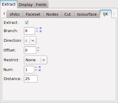
The "ijk" method requires three important parameters (or properties) to be set: The branch number, the direction, and the offset. The "branch" number is the number of the structured block from which the extraction is started. The "direction" can be understood as the normal vector of the ijk-plane. It is either "i", "j", or "k". The "offset" is the number of cells in "direction" from the origin (position 0, 0, 0) of the block, thus starting from 0.
For example, block 8 consists of 28 cells in i-direction, 92 cells in j-direction, and 24 cells in k-direction. The values "8" for "branch", "i" for "direction" and "28" for "offset" thus extract the second face of block 8.
p.ijk.branch = 8
p.ijk.direction = 'i'
p.ijk.offset = 28
It is possible to increase the "offset" beyond the confines of the block or to even specify negative values for "offset". In this case, baspl++ will attempt to "walk" along (or against) the specified direction until the desired value for the offset is matched. If this is not possible (because no elements are defined there), nothing will be extracted.
The extraction can optionally be restricted to the starting block. This is the block (or branch) from which the first matching face is extracted.
Finally, there is the possibility to extract more than a single ijk-plane. The planes are all oriented normal to "direction" and are separated by "distance" cells from each other. The "num" property defines how many planes baspl++ should attempt to extract.
p.ijk.distance = 10
p.ijk.num = 5
In the above example, the planes would be located at offsets 28, 38, 48, 58, and 68, respectively.
