|
|
|
A Timoshenko type beam element has been added to B2000++. Based on the developments by Simo and Vu-Quoc [1], Jelenic and Crisfield [2] , and others, it contains all the features required for a state-of-the-art beam element, such as
The element is implemented with the total Lagrangian formulation, as is the case for all B2000++ non-linear elements. Thus, the element is path-independent. Furthermore, with the local rotation interpolation technique proposed by Jelenic and Crisfield, the element is invariant to large rigid body rotations. 2 node beam elements and 3 node beam elements are available.
Beam cross section constants can be obtained for a limited set of section shapes. For arbitrary cross section shapes, a preprocessing facility for computing beam section properties for arbitrary open and closed, thin-walled or thick-walled beam sections, has been developed.
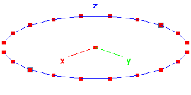
The capabilities of the element are illustrated with the "deployable ring" problem, one of the B2000++ test cases (see test case documentation): A thin elastic ring is clamped in one point and a rotation in the radial direction of the point opposite to the clamped point is applied. The rotation ranges from 0 to 2π. This problem has been described by Y. Goto et.al. and has been studied, among others, by Rebel[3], although with shell elements.
The FE mesh consists of 20 B2.S.RS elements, although, as tests have shown, 12 B3 elements would be sufficient to reproduce the results reported by Rebel. The mesh is displayed to the right, showing the geometry and mesh points as well as the application point of the rotation (left blue node) and the clamped point (right blue node). Note that the load is applied with a prescribed rotation in the global x-direction.
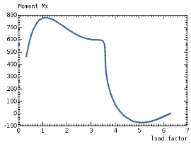
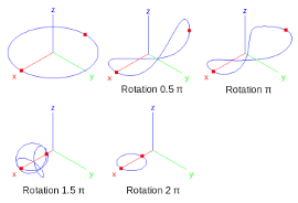
Results obtained with B2000++ are displayed in the two figures below. The graph displays the applied moment Mx due to the applied rotation in the global x-direction, i.e the reaction to the applied rotation, as a function of the applied rotation. The deformation process is illustrated in the figure to the right, displaying steps corresponding to 0.5π, π, 1.5π, and 2π.
Test cases for the new beam element are available, among them the 45° bent cantilever, the Lee frame, and the deployable ring. The tests check the obtained loading curves with reference curves and report any deviation beyond a given threshold.
[ 1 ] J.C. Simo L. Vu-Quoc; A three-dimensional finite-strain rod model; Comput. Methods Appl. Mech. Engrg. 58 (1986).
[2] G. Jelenic and M.A. Crisfield; Geometrically exact 3D beam theory: Implementation of a strain-invariant finite element for static and dynamics; Comput. Methods Appl. Mech. Engrg. 171 (1999).
[3] G. Rebel; Finite Rotation Shell Theory including Drill Rotations and its Finite Element Implementation; PhD Thesis, Delft University Press (1998).
Added 24 March 2011 and updated 26 June 2012