|
|
|
In certain situations, like during optimization, it is desirable to move parts of a FE mesh around, such as stiffeners on panels, without having to re-mesh the complete model. This can be achieved with non-matching grids and a suitable method for coupling or tying the grids together.
B2000++ ties non-matching grids with a kinematic coupling method referred to as the common mesh refinement method. While the grid nodes of two non-matching grids do not have to match, the surface on which the grid nodes are placed must more or less coincide. The figures below illustrates the concept.
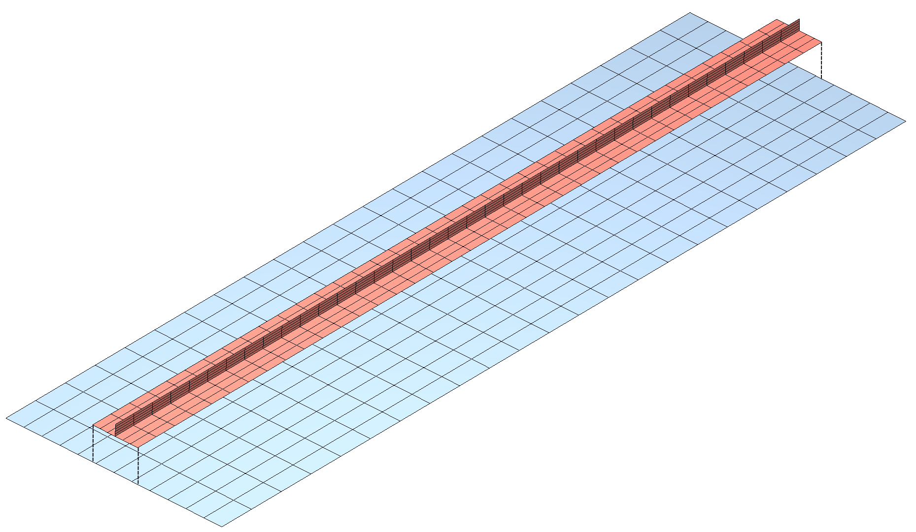
A plate (blue) mesh and a stiffener mesh with foot (red, displayed with an offset) do not match, but the element nodes are on a the common surface. |
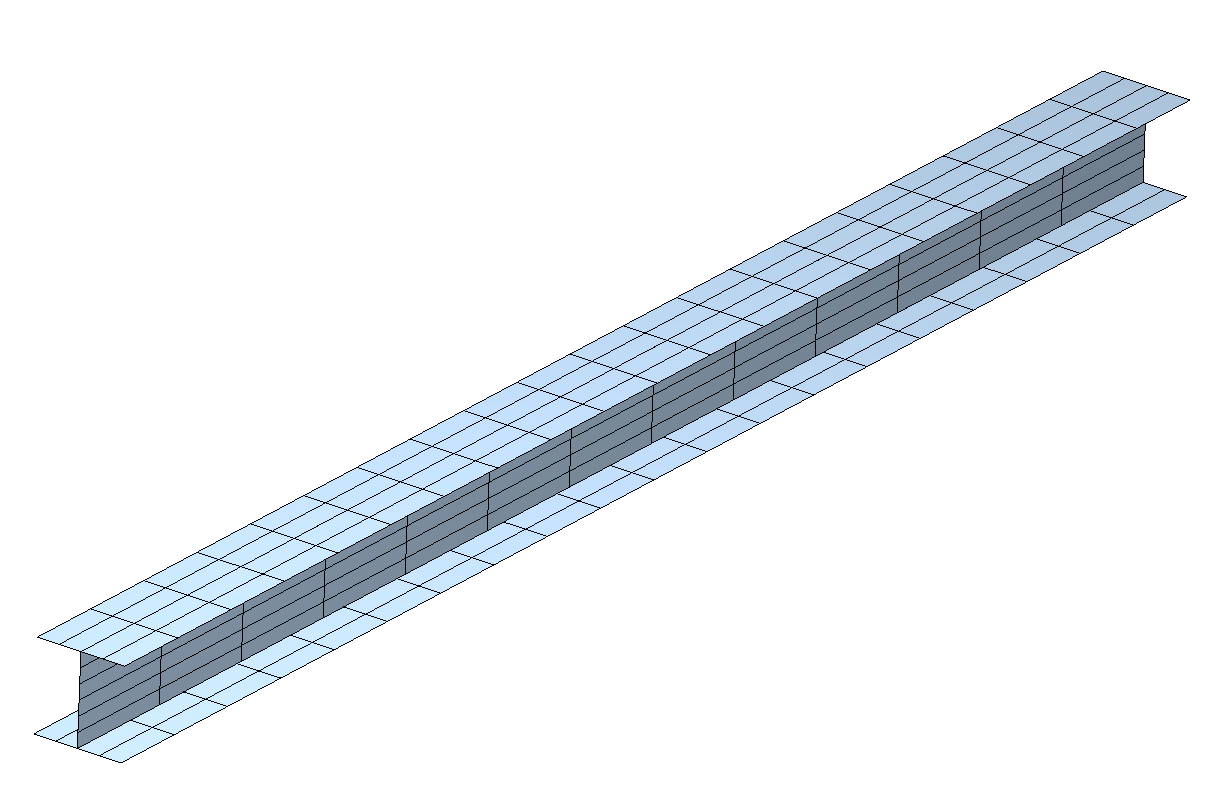
The model of an I-profile beam meshed with shell elements consists of 3 patches, the top and bottom flanges, and the web. Flange and web meshes do not match, but the element nodes are on a the common surface. Find out [more] about the shell model and find out [more] about the solid model. |
The tying instructions in the MDL input file are simple: Each pair of surfaces to be coupled must be defined in a field_transfer block identified by a positive integer. In the case of the plate with a stiffener above this would be
field_transfer 123
   # Tie stringer foot to plate
   interface 1 faceset "stringer_foot"
   interface 2 faceset "plate"
   transfer displacement minimise_on interface 2
end
which means that the stringer foot element faces are coupled to the plate element faces. The tying instruction is similar to a boundary condition definition and each tying instruction is activated for a specific case in the MDL case specification:
case 1
   ebc ... # Displacement constraints
   nbc ... # External forces
   field_transfer 123 # Activate tying with identifier 123
end