Datasets
This section describes all B2000++ datasets. Please observe the following conventions for dataset names and dataset name attributes:
Dataset names printed in upper-case are fixed names.
Dataset name fields printed in lowercase mean that the corresponding field is variable and will be substituted.
Branch identifiers:
branchmeans branch identifier (a positive integer). The branch identifier is either external or internal, depending on the context.Identifiers:
identmeans identifier. It is in most cases an integer. Depending on the context, an identifier can also consist of a string. An external identifier can have any positive integer value. Internal identifiers are numbered consecutively, starting at 1 (a Fortran heritage).cycle,subcycle,case,subcase,modeare all integers.
Analysis directives |
|
Fscon node coupling tables |
|
Beam section solver constitutive matrix |
|
Branch description tables |
|
Analysis case descriptions |
|
Mesh node coordinates |
|
Branch element integration point coordinates |
|
Initial conditions (dynamic analysis) |
|
Derivatives of initial condition with respect time |
|
Solution fields |
|
Essential boundary conditions |
|
Selected element edges set |
|
Solution fields defined per element, usually gradients |
|
Parameters describing element type |
|
Selected elements set |
|
Branch element integration point identifiers |
|
Description of element mesh patches |
|
Element description tables |
|
Selected element face set |
|
Solution fields parameter list |
|
Branch element integration natural coordinates |
|
Branch connectivity list |
|
Linear constraints |
|
Mass summary |
|
Material descriptors |
|
Natural boundary conditions |
|
Node-local transformations |
|
Additional node parameters |
|
Parameters describing node type |
|
Node normals |
|
Selected node set |
|
Element property tables |
|
Solution summary |
|
Solution stage summary |
|
Solution step summary |
|
Sampling point field |
|
Problem title |
|
Transformations (DOF transformations) |
|
Element volumes |
EDGELIST |
Selected element edges list (replaced by EDGESET). |
ELEMENTLIST |
Selected element set (replaced by ELEMENTSET). |
FACELIST |
Selected element face list (replaced by FACESET). |
NODELIST |
Selected node list (replaced by NODESET). |
ADIR
The analysis directives table contains the top-level information on
the problem (an array of MemCom dataset type I) . The information
in``ADIR`` is split into two parts, of which one is stored in the
descriptor and the other in the data set. While the descriptor of
ADIR contains essential top-level analysis control parameters and
some optional parameters, the data set contains a list of the branch
identifiers.
Content of Dataset Descriptor
The following keywords are always present in the ADIR descriptor. In
addition, other global keywords can be added, depending on the
program context.
Keyword |
Type |
Description |
|---|---|---|
|
Type of analysis. Optional, if omitted, a linear analysis is assumed. |
|
|
Array containing the ‘load’ cases to be processed. |
|
|
Total number of active and passive branches. |
|
|
Name of program that generated this database. |
|
|
Array containing program version (major, minor, cycle). |
Content of Dataset
Array of type I containing the list of the external branch
numbers. The external branch numbers can be listed in any order. If a
single branch is defined, its identifier must be 1.
Access
ADIR is created by the input processor and is
updated as required by other B2000++ applications.
AE-CPL-NODES
A fluid-structure interaction coupling table generated by the Fscon coupling tool and used in the special coupling boundary condition NSMB_MPI_Coupling. NSMB_MPI_Coupling is the coupling interface to the NSMB CFD solver.
Content of Dataset
Array of type I containing rows of (iid, mask, zero), where
iid is the B2000++ internal node identifier and mask and
zero are generated by Fscon.
BCS_CONSTITUTIVE_MATRIX.0.0.ident
The beam section solver constitutive matrix contains the 6 by 6 beam
section solver constitutive matrix (an array of MemCom dataset type
F).
Content of Dataset Descriptor
Keyword |
Type |
Description |
|---|---|---|
|
F (float64) |
Total mass (per unit length) of section. |
|
F (float64) |
Position y and z of the center of gravity with respect to section FE model coordinate system. |
|
F (float64) |
Mass inertia moments yy, zz, and yz. |
|
F (float64) |
Position y and z of the neutral axis with respect to section FE model coordinate system. |
Content of Dataset
6 by 6 beam section solver constitutive matrix stored row-wise as an one-dimensional array.
BDTB.branch
The branch mesh description table (a relational table of MemCom
dataset type $) contains the primary information on a branch,
storing parameters such as the type of the mesh, the number of nodes,
elements, grid lines etc.
Content of Dataset
Relational table containing the following keys:
Keyword |
Type |
Description |
|---|---|---|
|
Array defining the branch-global to global-global coordinate transformation matrix (optional). The array contains the translation vector and the rotation matrix (row-wise) for transforming branch-global coordinates to global-global coordinates. If omitted, the orientation of the branch is the same as the global orientation. See comment below. |
|
|
Array containing a list with all internal element type numbers used in this model (required). See dataset ELEMENT-PARAMETERS for the definition of the element type number. |
|
|
Type of mesh. For B2000++ meshes |
Access
BDTB is created by the input processor and is updated as
required by other B2000++ programs.
Additional Information
BTRF defines the translation and rotation transformation from the
branch-global to the global-global coordinate system. The first 3
array elements of BTRF contain the translation vector t with
respect to the global coordinate system. The array elements 4 to 12
define the rotation matrix base vectors e (row-wise)
t1,t2,t3,e11,e21,e31,e12,e22,e32,e13,e23,e33
ti are 3 translation vector coefficients and ei the 3 rotation
matrix base vectors.
CASE.case
The analysis case (“load case”) description tables list all parameters
of a case to be processed by the relevant solver. CASE.case is an array of
relational tables of MemCom dataset type $. Parameters include
essential and natural boundary conditions identifiers (like ‘forces’,
‘heat’, etc.), links between branches, constraint equations, etc. All
parameters specified by CASE.case will be combined to
form a single pair of essential and natural boundary conditions. Note
that the case identifier case is a positive integer.
Content of Dataset Descriptor
The descriptor contains all parameters common to all components of the case.
Keyword |
Type |
Description |
|---|---|---|
|
Name of equation (DOF) solution dataset to be generated for
this case. The name is usually of the form |
|
|
Gradient computation flag. |
|
|
Gravity acceleration vector \((g_x, g_y, g_z)\). If no gravity has been specified this key is not defined. |
|
|
Name of the natural boundary condition set to be generated for
this case. The name is usually of the form |
|
|
Type of reaction force restriction (if applicable, i.e. defined
in the input). Values are |
|
|
Data set name of the residuum set to be generated for this
case. The name is usually of the form |
|
|
Size of the initial load step. Defined during non-linear analysis only. |
|
|
Size of the minimum load step. Defined during non-linear analysis only. |
|
|
Size of the maximum load step. Defined during non-linear analysis only. |
|
|
Optional short description of the case. |
Content of Dataset
One or more of relational table sub-sets, each of them describing a component contributing to the current case:
Keyword |
Type |
Description |
|---|---|---|
|
Name of component. Currently, the following names are defined:
|
|
|
Type of component to the current case. |
|
|
Identifier of component. Usually a data set name of the form
|
|
|
Scale factor. If omitted the default scale factor of 1.0 is assumed. |
Access
CASE is created by the input processor
and is updated as required by other B2000++ programs, such as the B2000++ solvers.
Validity
Required. B2000++ cannot compute a solution without at least one CASE
dataset.
COOR.branch
The mesh nodes coordinate array (of MemCom dataset type F)
contains all node coordinates of a branch, the internal node numbers
being implicit: The first row of the array contains the coordinates of
internal node 1 (B2000++ database numbering convention!) or node 0 (C++,
Python, Simples,), the second row the coordinates of internal node
2(B2000++ database numbering convention!) or node 1 (C++, Python,
Simples,), and so on. The external node number of any internal node
number is stored in the node parameter list NODA.branch. The
coordinates of an internal node are always formulated in the branch
global three-dimensional Cartesian coordinate system.
Content of Dataset
Array of F``e floats with ``NN rows and 3 columns, where NN is
the number of nodes in the branch and is equal to size of the
array. The point storage scheme assumes values to be stored as follows
x1,y1,z1,x2,y2,z2,...,xn,yn,zn
with x designating the x-coordinate, y the y-coordinate, and z the z-coordinate. Note that coordinates are always stored for all 3 dimensions. The z-coordinate must be set to 0.0 for a 2-dimensional problem!
Access
COOR.br is created by the input processor and it can be modified by any
processor.
COOR_IP.branch.0.0.ident
The gradient integration point coordinates table (a MemCom array table
of type AT) contains the branch global Cartesian coordinates of
all defined integration points. COOR_IP is used together with
ELEM_IP.branch.0.0.case, IP.branch.0.0.case`, and the sampling-point solution sets
to manage the sampling point solution data.
Content of Dataset
Array table with 3 columns containing the 3 global Cartesian coordinates. There are as many rows as there are integration points for the current branch.
Access
Created by the solver processor and it can be modified by any processor.
DOF_INIT.branch.0.0.ident
Specifies the optional initial boundary condition list (a MemCom F
array) for a given branch and identifier ident (a positive
integer). Initial DOF condition lists will then be activated by an
entry in a case definition.
The initial boundary conditions are specified with respect to
the reference coordinate system defined by the SYSTEM type (see
below).
Content of Dataset Descriptor
Keyword |
Type |
Description |
|---|---|---|
|
Reference coordinate system of the essential boundary
conditions described by this set. |
Content of Dataset
Array with a variable number of rows and 3 columns. Column 1 contains the internal node number (B2000++ internal numbering, a positive int starting at 1) or internal element number (a negative int starting at -1) identifier. Column 2 contains the DOF. Note that DOFs are numbered 1,2,3,…. Column 3 contains the boundary condition value.
Access
DOF_INIT is created by the input processor if initial conditions are specified and it is
referenced by the CASE.case sets, i.e. CASE.case sets will
tell relevant B2000++ processors which initial conditions to include in
an analysis.
Validity
DOF_INIT is required whenever initial boundary conditions are
present.
DOFD_INIT.branch.0.0.ident
Specifies the optional time derived initial boundary condition list (a
MemCom F array) for a given branch and identifier ident (a
positive integer). The time derived initial boundary conditions are
specified with respect to the reference coordinate system defined by
the SYSTEM type (see below).
Content of Dataset Descriptor
Keyword |
Type |
Description |
|---|---|---|
|
Reference coordinate system of the essential boundary
conditions described by this set. |
Content of Dataset
Array with a variable number of rows and 3 columns. Column 1 contains the internal node number (B2000++ internal numbering, a positive int starting at 1) or internal element number (a negative int starting at -1) identifier. Column 2 contains the DOF. Note that DOFs are numbered 1,2,3,…. Column 3 contains the boundary condition value.
Access
DOFD_INIT is created by the input processor if time derived initial conditions and it is
referenced by the CASE.case sets, i.e. CASE.case sets will
tell relevant B2000++ processors which initial conditions to include in
an analysis.
Validity
DOFD_INIT is required whenever initial boundary conditions (time
derivatives) are present.
DOF Solution Field
DOF solution fields are 2-dimensional arrays identified by
gname.branch.cycle.subcycle.case[.subcase]
DOF solution fields contain the problem solution fields for all
DOFs at all DOF evaluation points, usually the mesh
nodes (a MemCom F array). Any specific DOF is defined by
the node type, see NODE-PARAMETERS. The generic dataset name
is usually defined in the CASE.case dataset descriptor. Common
DOF field generic field names gname are DISP
(i.e. displacements), FORC (forces), RCFO (reaction forces),
or TEMP (temperatures) and HEAT. A summary of the currently
defined DOF fields can be found in DOF Fields.
Content of Dataset Descriptor
Keyword |
Type |
Description |
|---|---|---|
|
Reference system. |
|
|
Type of DOF field. Currently only |
Content of Dataset
Two-dimensional array of F type floats with NN rows and one or
more columns (NN is equal to the number or mesh nodes).
Access
The set is created by B2000++ solvers.
EBC.branch.0.0.ident
Essential boundary conditions specify constraints on node (or
elements) for a given branch and identifier ident (a MemCom F
array) . The essential boundary conditions are described with respect
to the domain defined by the DOMAIN type (see below) and they
relate to the reference coordinate system defined by the SYSTEM
type (see below).
Content of Dataset Descriptor
Keyword |
Type |
Description |
|---|---|---|
|
Type of domain to which the essential boundary conditions
described by this set pertain. |
|
|
Field type of the essential boundary conditions described by this set.``VALUE`` means degrees of freedom. |
|
|
Reference coordinate system of the essential boundary
conditions described by this set. |
Content of Dataset
Two-dimensional array of F floats containing as many row as there
are boundary conditions. A column contains:
Domain type
DOF: Column 1 contains the internal node identifier (a positive int value) or element identifier (negative value). Column 2 contains the degree of freedom number. Column 3 and up contain the boundary condition value(s).Domain type
EEDGE: Column 1 contains the internal element identifier (a positive int value). Column 2 contains the element local element edge number (see Generic Elements). Columns 3 and up contain the boundary condition values defined byTYPE.Domain type
EFACE: Column 1 contains the internal element identifier (a positive int value). Column 2 contains the element local element face number (see Generic Elements). Columns 3 and up contain the boundary condition values defined byTYPE. If the field type isPRESSURE, a single value for a given face is defined, and the a positive pressure acts in the direction of the face normal. For all other field types, all components pertaining to the specific field type are defined (usually 3).Domain type
EBODY: Column 1 contains the internal element identifier (a positive int value). Columns 2 and up. contain the boundary condition values defined by the field typeTYPE. If the field type isHEAT, a single value for a given DOF is defined. For all other field types, all components pertaining to the specific field type are defined (usually 3).
Node and element identifiers, as well as DOF, element face and edge identifiers must be converted from float to integer!
Node and element identifiers are internal and start with index 1. Edge and face numbers are defined in the Generic Elements section of the user manual.
Access
EBC.branch.0.0.ident is created by the input processor and is updated as required by other processors
or control modules.
Validity
EBC.branch.0.0.ident is required whenever essential boundary
conditions are present.
ELEMENTSET.branch.0.0.name
The selected elements set array contains a list with element
identifiers defined for branch branch (a MemCom I
array). name is the set name.
Content of Dataset Descriptor
Keyword |
Type |
Description |
|---|---|---|
|
Indicates whether the set is unique and sorted (1) or unsorted (0). |
Content of Dataset
Array of I (integer) values containing internal element identifiers.
Access
Created by the input processor.
Element Solution Field
Element solution fields gname.branch.cycle.subcycle.case[.subcase]
are MemCom F arrays containing element solution values. Not to be
confused with Sampling Point Solution Fields.
Content of Dataset
Two-dimensional array of F type floats with as many rows as there are
elements in the branch. Each gname field can define one or more
columns. A summary of the currently defined element fields can be
found in the section Selected Datasets.
Access
Created by the relevant B2000++ solvers.
ELEM_IP.branch.0.0.case
Element integration point identifiers (MemCom array tables of type
AT) contain the branch integration point identifiers for elements
of a analysis case. ELEM_IP is used together with
COOR_IP, IP, and the sampling-point solution sets to manage
the sampling point solution data per load case case.
Content of Dataset
Array table with 2 columns containing the element number and the integration point number. There are as many rows as there are integration points for the current branch.
Access
COOR_IP is created by the solver processor and it can be modified by any processor.
ELEMENT-PARAMETERS
The element parameter table ( a set of MemCom $ tables) specifies
the relation between the unique element name and the unique internal
element number as well as other element parameters.
Content of Dataset
Array of relational tables, each of them containing the parameters of a given element type:
Keyword |
Type |
Description |
|---|---|---|
|
Set to 1 if the element is a candidate to |
|
|
Internal element number of this element. |
|
|
Length of temperature array. |
|
|
Element name. |
|
|
Array containing the node type numbers of all element nodes as defined by NODE-PARAMETERS. |
Element Name Conventions
Element name conventions are important for -among others - the
baspl++ processor. baspl++ is independent of B2000++ but has a
built-in knowledge of the B2000++ element naming conventions and the
conventions used to enumerate nodes, edges, element faces, etc.
Element names consist of the generic element name gname followed
by attributes, all of them in upper case. The generic name contains
several fields separated by dots. The first field describes the element
shape and the number of nodes defining the element (see table below).
Shape |
Description |
|---|---|
C |
Solid mechanics cable elements. |
R |
Solid mechanics rod and cable elements (rods are similar to beams, but they exhibit axial stiffness only). |
T |
Generic triangular element. |
Q |
Generic quadrilateral element. |
HE |
Generic hexahedral element. |
TE |
Generic tetrahedral element. |
PR |
Generic prism (‘wedge’) element. |
PY |
Generic pyramid element. |
Access
ELEMENT-PARAMETERS is created by the input processor.
Validity
ELEMENT-PARAMETERS is required.
EDGESET.branch.0.0.name
The selected element edge set array contains a list with element edges
defined for branch branch (a MemCom I array) . name is the set
name.
Content of Dataset Descriptor
Keyword |
Type |
Description |
|---|---|---|
|
Indicates whether the set is unique and sorted (1) or unsorted (0). |
Content of Dataset
Two-dimensional array of I (integer) values with NROW rows and 2 columns. NROW is the number of pairs (element_id, edge_id). Column 1 contains the internal element identifier and column 2 the edge number.
Access
Created by the input processor.
EPATCH.ident
The MDL mesh patch relational table
contains the parameters describing a mesh patch identifies ident (a
positive int). The patch will be generated in the input processor,
storing the generated nodes, elements and element and node lists on
the database.
Note
Use of EPATCH is discouraged.
identdoes NOT refer to branch (the branch identifier is stored in the descriptor),
Content of Dataset
Relational table containing the parameters describing a mesh patch:
Keyword |
Type |
Description |
|---|---|---|
|
Branch number to which patch belongs. |
|
|
Element type name. |
|
|
Patch geometry type. |
|
|
Number of elements in i-direction. |
|
|
Number of elements in J-direction. |
|
|
Number of elements in K-direction. |
|
|
Patch placement in space. Array with 12 elements (3 translations and 3 orientation points). The definition id the same as for node transformations, see TRANSFORMATIONS. |
|
|
Start element index of patch element numbering.Element identifiers will be incremented by 1 for each node generated. |
|
|
Start node index of patch node numbering. Node identifiers will be incremented by 1 for each element generated. |
Keyword |
Type |
Description |
|---|---|---|
|
Definition of a point |
|
|
Thickness of patch. Applies to element types requiring specification of thickness. |
|
Others |
Geometry-dependent, such as |
Additional Information
The following datasets are generated together with EPATCH for a given patch identifier id:
EDGESET.branch.0.0.EPATCH-ident-Ex: List of pairs (element-index,edge-identifier) for branchbranch, patchident, and edgeEx.ELEMENTSET.branch.0.0.EPATCH-ident-B: List of all internal element indices for branchbranchof patchident.FACESET.branch.0.0.EPATCH-ident-Fx: List of pairs (element-index,face-identifier) for branchbranch, patch ident`, and faceFx.NODESET.branch.0.0.EPATCH-ident-B: List of all internal node indices for branchbranch, patchident.NODESET.branch.0.0.EPATCH-ident-Ex: List of (node-id) for branchbranch, patchident, patch edgeEx.NODESET.branch.0.0.EPATCH-id-Fx: List of internal node indices for branchbranch, patchident, patch faceFx.
Access
EPATCH.ident is created by the input processor.
ETAB.branch
The element description tables contain all properties of every element
of the branch mesh, referring, when required, to other properties,
such as property tables or material table. Please refer to the element
specific ETAB sections of Chapter Selected Datasets. If, for a
specific element, no ETAB section is available, the properties
described in this section apply.
Content of Dataset
Sparse table (ST) with as many rows as there are elements in the branch. Each row contains all parameters of the element and is accessed with the same API as the one for MemCom relational tables. Element-type specific data is found in section Element Parameters.
Keyword |
Type |
Description |
|---|---|---|
|
External element identifier, a positive integer. |
|
|
Internal element type identifier, a positive integer. See ELEMENT-PARAMETERS. |
|
|
Material identifier, a positive integer. |
|
|
Array containing the internal element node indices defining the element, i.e. element connectivity list. Internal element node indices are positive integers. |
|
|
Property identifier, a positive integer. |
Access
ETAB.br is created by the input processor.
Validity
ETAB.br is required.
FACESET.branch.0.0.name
The selected element face set array contains a list with element faces
defined for branch branch (a MemCom I array) . name is the
set name.
Content of Dataset Descriptor
Keyword |
Type |
Description |
|---|---|---|
|
Indicates whether the set is unique and sorted (1) or unsorted (0). |
Content of Dataset
Two-dimensional array of I (integer)
integers containing as many rows as there are list entries. Each row
list of pairs (elementid, faceid), where elementid is the
internal element identifier and faceid the element face number.
Access
Created by the input processor.
FIELDS
The field parameters summary tables (a set of MemCom relational tables) contain the parameters for all defined (solution) fields, such as the generic name of the field, the domain of validity, etc. Fields, such as DOF fields or Sampling Point fields, are generated as a function of the operator and the analysis type, and they contain displacements, temperatures, forces, stresses, etc. While the field parameters are not used by the B2000++ solvers, they are needed by other programs, such as baspl++ post-processor of the b2browser model browser..
Content of Dataset
Array of relational tables, each of the relational tables containing the following field parameters:
Keyword |
Type |
Description |
|---|---|---|
|
Additive field flag. Must be set to |
|
|
Discrete field flag. Must be set to |
|
|
Generic name of field. |
|
|
Indexed field flag. Must be set to |
|
|
Coordinate system. Branch means branch-related,
|
|
|
Short text describing the field (optional). |
|
|
Domain of validity of the field. |
Access
FIELDS is created empty by the input processor and is updated as required by the programs which
generate the specific fields.
Example
A standard deformation analysis DOF field (DISP) for a
solid analysis will have the following attributes:
'ADDITIVE': 'NO'
'DISCRETE': 'NO',
'GNAME': 'DISP',
'INDEXED': 'NO',
'TITLE': 'Displacements DX,DY,DZ',
'SYSTEM': BRANCH'
'TYPE': 'NODE'
Note
‘INDEXED’: ‘NO’ mans that the field contains all DOF values for all defined nodes, listed one after the other according to the internal numbering.
‘ADDITIVE’: ‘YES’ means that values across rows can be added (such as forces).
‘DISCRETE’: ‘YES’ means the values are discrete between nodes at which they are defined, i.e. interpolation is not admitted.
IP.branch.0.0.case`
Stores the gradient integration points natural coordinates (MemCom
array tables of type AT) for a given branch and case and is used
together with COOR_IP.branch.0.0.ident, ELEM_IP.branch.0.0.case, and the
sampling point solution sets to manage the sampling point solution
data.
Content of Dataset
Array table with 4 columns containing the 3 natural coordinates ()r,s,t) and the layer number. There are as many rows as there are integration points for the current branch.
Access
IP is created by the solver processor and it can be modified by
any processor.
JCTS
The branch node connectivity array (a MemCom I array) specifies
how branches are interconnected by mesh nodes.
Content of Dataset
I integer array with 6 columns and as many rows as there are
coupling conditions. A row contains
BRANCH1, NODE1, DOF1, BRANCH2, NODE2, DOF2
meaning that in the final equations the computational degree of
freedom corresponding to internal node NODE1 and degree of freedom
DOF1 of external branch BRANCH1 shall be equated to the degree
of freedom associated with internal node NODE2 and degree of
freedom DOF2 of external branch BRANCH2. If DOF1 is set to
0 the node NODE1, all degrees of freedom of internal node
NODE1 will be coupled to internal NODE2, and DOF2 is
ignored.
Note that the compound transforms (master-slave transforms) only apply
in case the nodes are fully coupled, i.e. if the node NODE1 is set
to 0.
Additional Information
Although branch node connectivity lists are most frequently used to link nodes, i.e. to fully couple branches, juncture conditions can require partial compatibility. Hinged joints are a possible application.
Access
JCTS is created by the input processor
and it is updated as required by other processors or control modules.
Validity
JCTS is required by the B2000++ solvers whenever more than one
branches are present and the branches are explicitly linked with the
MDL join command.
LINC[.ident]
The linear constraints list (a MemCom I array) contains all linear
constraint equations pertaining to a model. A constraint equation is
of the form
where \(c_i\) are real coefficients and \(u_i\) are the degrees of freedom involved. The coefficients \(c_i\) are normalized such that the largest of the coefficients is equal to 1. The constant \(c_0\) can, within reasonable limits, have any magnitude. It is not considered in the search for the largest coefficient.
Content of Dataset Descriptor
Keyword |
Type |
Description |
|---|---|---|
|
Number of linear constraint equations. |
Content of Dataset
One-dimensional array of F type floats storing the constraint equations one after the other. Each constraint equation is described by
N,WEIGHT,C0,BRANCH1,NODE1,DOF1,C1, ..., BRANCHN,NODEN,DOFN,CN
where N is the number of terms inthe constraint equation,
WEIGHT is the weight for the current constraint equation, and
C0 the constant \(c_0\). For each coefficient the external
branch number BRANCH, the internal node number NODE, the
degree of freedom DOF, and the coefficient C must be
specified. BRANCH, NODE, and DOF will be used to calculate
the global degree of freedom number i for the component \(c_i
\cdot u_i\). Thus, the number of floats for describing the equation is
4N+3.
Access
LINC is created by the input processor.
Validity
LINC is required if linear constraint equations are present in a model
and if they are required by the LINC option of the CASE.case command.
MATERIAL.<mid>
The element material properties table (MemCom relational table) is a
container for storing all parameters of an element material identified
by <mid> (a positive int).
Content of Dataset
Relational table describing a specific material. Material property parameters are dependent on the type of material. Specific material are described in the Context-Dependent Datasets section.
Keyword |
Type |
Description |
|---|---|---|
|
Descriptive material subtype, such as |
|
|
Descriptive material type, such as |
Access
MATERIAL.<mid> is created by the input processor and is accessed by the material classes of
B2000++.
MASS_AND_COG.branch
Mass and volume summary table (a MemCom relational table of type
$).
Content of Dataset
Relational table containing the mass and volume of the complete mesh of the branch as well as the element sets.
Access
MASS_AND_COG is created by the b2mass
application.
Validity
Optional.
NBC.branch.0.0.ident
A natural boundary condition list (a MemCom F type array) contains
a specific type TYPE of natural boundary conditions for a given
branch and identifier ident (a positive int). The natural boundary
conditions are described with respect to the domain defined by the
DOMAIN type (see below) and they relate to the reference
coordinate system defined by the SYSTEM type (see below).
Content of Dataset Descriptor
Keyword |
Type |
Description |
|---|---|---|
|
Type of domain to which the natural boundary conditions
described by this set pertain. |
|
|
Field type of the natural boundary conditions described by this
set: |
|
|
Reference coordinate system of the natural boundary conditions
described by this set. |
Content of Dataset
Array of F type floats with as many row as there are noundary
condition entries. The number of columns depends on TYPE:
Domain type
DOF: Column 1 contains the internal node or element identifier. Note that, for the domain typeDOF, the element identifier is a negative number to discern it from the node identifier. Column 2 contains either the degree of freedom number (field typeVALUEonly). Columns 3 and up contain the boundary condition values defined byTYPE. IfTYPEisVALUE, only one single value for a given DOF is defined. For all otherTYPEtypes, all components pertaining to the specificTYPEare defined.Domain type
EEDGE: Column 1 contains the internal element identifier (positive integer) and column 2 contains the element edge number. The Generic Elements section of the B2000++ Model Description Language User Manual describes the local element edge numbers for all element types. Columns 3 and up contain the boundary condition values defined byTYPE. IfTYPEisHEAT, orPRESSURE, only one single value for a given DOF is defined. For all otherTYPEtypes, all components pertaining to the specific field type are defined (usually 3).Domain type
EFACE: Column 1 contains the internal element identifier and column 2 contains the element face number. The Generic Elements section of the B2000++ Model Description Language User Manual describes the local element face numbers for all element types. Columns 3 and up contain the boundary condition values defined byTYPE. IfTYPEisHEAT, orPRESSURE, only one single value for a given DOF is defined. For all otherTYPEtypes, all components pertaining to the specific field type are defined (usually 3).Domain type
EBODY: Column 1 contains the internal element identifier and column 2 and up contain the boundary condition values defined by theTYPE. IfTYPEisHEAT, orPRESSURE, only one single value for a given DOF is defined. For all otherTYPEtypes, all components pertaining to the specific field type are defined (usually 3).
Node and element identifiers are internal and start with index 1. Edge and face numbers are defined in the Generic Elements section of the user manual. If the node/elem identifier is positive the identifier is a node. If it is negative, the identifier is an element and the sign must be changed.
Access
NBC.branch.0.0.ident is created by the input processor and is updated as required by other processors
or control modules. The NBC sets are referenced by the CASE.case
sets.
Validity
NBC.branch.0.0.ident is required whenever natural boundary
conditions are present.
NODE-PARAMETERS
The node parameter table (a set of MemCom relational tables) defines the node properties of each node type, such as the type of node or the nodal freedom pattern. The node parameters are defined once during a database creation run, i.e. the initial input processor run. All node parameters must remain constant throughout the computations.
Content of Dataset
Node parameters stored in an array of relational tables. Each table contains the following node property parameters:
Keyword |
Type |
Description |
|---|---|---|
|
Node type name. |
|
|
Node type number. Must be greater than 0. |
Access
NODE-PARAMETERS is created by the input processor. In the current 4.6 it is created by the
function save_node_parameters() in src/b2ip_model.C.
NODESET.branch.0.0.name
The selected nodes set array contains a list of selected nodes of a
branch branch (a MemCom I``type array). ``name is the set
name.
Content of Dataset Descriptor
Keyword |
Type |
Description |
|---|---|---|
|
Indicates whether the set is unique and sorted (1) or unsorted (0). |
Content of Dataset
Array of I (integer) integers containing internal node identifiers.
Access
Created by the input processor.
NLCS.branch Node-local transformations
The node-local transformations arrays contain the node-local rotation
matrices (a MemCom F type array). The transformation is defined as
where \(u_{nl}\) is a vector formulated with respect to the node-local system and \(u_{bg}\) to the branch global system. The transformation \(T\) contains the 3 normalized base vectors \(e_i\) row-wise. The vectors \(e_i\) are the base vectors of the node-local system with respect to the branch-global system. Node local systems are useful for defining special boundary conditions or for expressing solutions in surface coordinates.
Content of Dataset
Two-dimensional array nlcs[nrows, 9] of F type floats. The
number of rows in the set corresponds to the number of node-local
systems of the current branch. Each row contains the 3 by 3 rotation
matrix stored row-wise. The node attribute table NODA
points to the row containing the rotation matrix.
Access
NLCS.br is generated by the input processor: All nodes are scanned
for the dofref attribute. If dofref>0 the corresponding
transformation is applied and the transformation matrix added to
NLCS.br (in ascending internal node order, i.e 0, 1, 2…). Note
that other sources than the input processor can produce
transformations, i.e dofref is not necessarily at the origin of
the node-local transformation matrix of a node!
Validity
NLCS is required if node-local transformations are present, the
node-local transformation identifiers stored in the third column of
NODA pointing to the corresponding row - 1 of NLCS.
NODA.branch
The NODe Attribute table (a MemCom I type array) contains
additional attributes of each mesh node. The mesh node coordinates
table COOR.branch (a MemCom F type array), together with the
node attribute table NODA.branch, describe the mesh nodes. Note
that the node coordinates and the node attributes refer to the
internal continuously numbered node indices. These are in the range of
1 to NN, where NN is equal to the number or rows of
COOR.branch and NODA.branch.
Content of Dataset
Two-dimensional array of I integers with NN rows and 4 columns. A
row of NODA.branch contains the following attributes:
Column 1 contains the external node identifier
EID(a positive integer) of the internal node described by the current row index. Note that B2000++ internal row indexes start with the index 1.Column 2 contains the node-local transformation matrix index
NLCS_INDEX(a positive integer or 0) pointing to the node-local transformation matrix of that node (see:ref:NLCS <db.NLCS>). value of 0 means that there is no node-local transformation.Column 3 contains the node-local transformation
TRANSFORM_INDEXidentifier (a positive integer or 0) as defined by the MDL command transformations and referred to by thedof_refparameter of the MDL nodes command. A value of 0 means that there is no node-local transformation.Column 4* contains the node type
NODE_TYPEidentifier as described by the dataset NODE_PARAMETERS. Node type identifiers start with the index 1.
Additional Information
A node with the internal node index i which has a local coordinate
system will have an index k>0 in the second column of
NODA. The index k then points to the row k of the
NLCS.branch Node-local transformations array (k-1 for C/C++/Python arrays!). Example
(C++): Get transformation matrix of node 123:
int i = 123;     // Internal node identifier (numbering starts with 1)
mcInt32 *noda;   // Node attribute array [4*n]. Assumed to be loaded.
mcFloat64 *nlcs  // Local transform array [9*n]. Assumed to be loaded.
mcFLoat64 *tmatrix // Rotation matrix pointer
int k = noda[(i-1)*4 + 1] // Index of local transform (column 2 of noda)
if (k > 0)
    *tmatrix = nlcs[ (k - 1)*9 ] // Transformation matrix
Access
NODA.br is created by the input processor.
Validity
NODA.br is required.
NODE-NORMALS.branch
The node normals array (a MemCom F type array) contains the list
of all node normal vectors of a branch. The node normal vectors must
be normalized to 1 and are always formulated in the branch global
Cartesian coordinate system. Nodes without normals will have zero
values.
Content of Dataset
Array of F type floats with NN rows and 3 columns, where NN is
the number of nodes in the branch (NN is equal to the number or
rows of COOR.branch.
Access
NODE-NORMALS.branch is created by the input processor and can be
modified by any processor.
Validity
NODE-NORMALS.br is optional. It is usually present if curved shell
structures are defined.
PROPERTY.<pid> Element properties
The element property table (a MemCom relational table) describes
property type dependent element parameters referenced by the property
identifier <pid>.
Property type BEAM_CONSTANTS
TYPE BEAM_CONSTANTS describes a beam section by all relevant
constants. They can be either defined by the cross section or
stiffness constants, which allow for a more general definition, i.e
for non-homogeneous materials.
Keyword |
Type |
Description |
|---|---|---|
|
Total cross-sectional area \({A}\). |
|
|
Array containing second moments of area, \(I_{yy}\), \(I_{zz}\) and \(I_{yz}\) about the centroidal axes. |
|
|
Array containing bending stiffness coefficients \(E I_{yy}\),
\(E I_{zz}\) and \(E I_{yz}\) (floats). If
|
|
|
Mass \(\rho A\) per unit length of beam. If |
|
|
Array containing the section coordinates \((y_m, z_m)\) of the mass center w.r.t. the section origin. Default is \((0, 0)\). |
|
|
Array containing mass inertia moments \(J_{yy}\), \(J_{zz}\) and \(J_{yz}\) about the mass center. |
|
|
Material identifier. Required. |
|
|
Array containing the section coordinates \((y_c, z_c)\) of the neutral axis point w.r.t. the section origin. Default is \((0, 0)\). |
|
|
Non-structural mass per unit beam length. Default is \(0.0\). |
|
|
Array containing section coordinates \((y_{ns}, z_{ns})\) of the non-structural mass center w.r.t. the section origin. Default is \((0, 0)\). |
|
|
Specifies an optional offset \((y_o, z_o)\) of the cross-sectional
coordinate system in the y-z-plane of the beam local system. Either
an array containing the y- and z-component of the offset (floats), or
one of the strings |
|
|
Array containing the section coordinates \((y_s, z_s)\) of the shear center w.r.t. the section origin. Default is \((0, 0)\). |
|
|
Array containing shear correction factors \({k_{yy}}\), \({k_{zz}}\) and \({k_{yz}}\). |
|
|
Array containing shear stiffnesses \({k_{yy} G A}\),
\({k_{zz} G A}\) and \({k_{yz} G A}\). If |
|
|
Array containing stress evaluation points at section coordinates \((y_i, z_i)\) w.r.t. the section origin. |
|
|
Whether to swap y- and z-axes dependent cross-sectional parameters. One
of |
|
|
Torsional constant \({I_t}\). |
|
|
Torsional stiffness \({I_t G}\). If |
|
|
Axial beam stiffness \({E A}\). If |
Property type BEAM_SECTION
TYPE BEAM_SECTION describes a beam section by section types according to the
MDL Manual. The element property table
contains parameters (keywords) that were set by the user. Additionally, it may
contain computed parameters, written back to the database by the
input processor.
Keyword |
Type |
Description |
|---|---|---|
|
Dimensions of section according to MDL Manual. |
|
|
Element material identifier. |
|
|
Non-structural mass per unit beam length (default: 0.0). |
|
|
Specifies an optional offset \((y_o, z_o)\) of the cross-sectional
coordinate system w.r.t. the beam local system, effectively shifting the
entire cross-section in the local y-z-plane. Either an array containing
the y- and z-component of the offset (floats), or one of the strings
|
|
|
Cross-sectional shape: One of |
|
|
Whether to swap y- and z-axes dependent cross-sectional parameters. One
of |
Keyword |
Type |
Description |
|---|---|---|
|
Total cross-sectional area \({A}\). |
|
|
Principal moments of area (\(I_1 > I_2\)). |
|
|
Torsional constant \({I_t}\). |
|
|
Second moments of area, \({I_{yy}}\), \({I_{zz}}\) and \({I_{yz}}\) (floats) about the centroidal axes. |
|
|
Shear correction factors \({k_{yy}}\) and \({k_{zz}}\) to account for non-uniform shear-stress distribution. |
|
|
Stress evaluation points at section coordinates \((y_i, z_i)\) w.r.t. the section origin. |
|
|
Torsion resistance moment \(W_t\), if defined. |
|
|
Angle between y-axis and principal y-axis. |
|
|
Section coordinates \((y_c, z_c)\) of the neutral axis point (centroid) w.r.t. the section origin. |
|
|
Section coordinates \((y_s, z_s)\) of the shear center w.r.t. the section origin. |
|
|
Coordinates \((y_{min}, z_{min})\) and \((y_{max}, z_{max})\) of lower-left and upper-right bounding box corner of the cross-section w.r.t. the section origin. |
Property type BEAM_SECTION_MESH
TYPE BEAM_SECTION_MESH describes the beam section by a FE
mesh. The preprocessor will then compute all required constants,
starting from the mesh and the material.
Keyword |
Type |
Description |
|---|---|---|
|
Material identifier. |
|
|
B2000++ MDL input file name describing section mesh and boundary conditions. |
Access
PROPERTY.pid is created by the input processor.
Validity
PROPERTY.pid is optional.
Sampling Point Solution Field
A sampling point field (MemCom ST table format) contains element
gradient fields, such as stress tensors or heat flow vectors. Each
element can contain a variable number of sampling points containing
one or more float values, usually gradients computed element-wise. The
number of sampling point values at any sampling point is constant
throughout the whole set. Sampling points are accessed by dataset name
and sampling point number.
Sampling point fields are identified by the dataset name
gname.branch.cycle.subcycle.case[.subcase]
The field attributes of a sampling points field described by gname
are contained in the :ref.`db.FIELDS` dataset.
Sampling point fields are addressed with the internal element identifier starting at 0 and ending at NE-1, where NE is the number of elements in the branch. If a specific element does not have a sampling point field it is up to the application to check.
A summary of the currently defined sampling point fields can be found in the Context-Dependent Datasets section.
Content of Dataset Descriptor
Keyword |
Type |
Description |
|---|---|---|
|
Dot-separated string containing the symbolic component names. |
|
|
Short text describing the field, such as “Cauchy stress”, “Green Lagrange strain”. |
|
|
Solution field type. Currently set to |
|
|
Reference to |
|
|
Path parameter. Non-linear static analysis only. |
|
|
Number of components of field. |
|
|
Computational stage identifier (nonlinear analysis). The stage identifier is identical to the case identifier of the stage as specified in the CASE.case definition. |
|
|
Internal stage identifier (nonlinear analysis). The internal
stage identifier is inserted by the solver and starts with 0
(first stage called in the computation). For each additional
stage the value for |
|
|
Reference coordinate system. |
|
|
Order of the tensor or -1 if not applicable. |
|
|
Size of the tensor or -1 if not applicable. |
|
|
Set to 1 if the tensor is symmetric and to 0 if not. If applicable. |
|
|
Integration time. Dynamic analysis only. |
Content of Dataset
Array table with NE rows, where NE is the number of elements in the
branch (equal to the size of dataset ETAB.branch).
Access
Sampling-point-fields are created by the B2000++ solvers.
Validity
Sampling-point-fields are optional. B2000++ computes sampling points
only if the GRADIENT parameter of CASE.case has a non-zero
value.
SOLUTION.0.0.0.case
The solution summary table (MemCom relational table) contains the
global solution attributes of the corresponding case identifier
defined by the dataset CASE.case.
Content of Dataset
Relational table containing global solution attributes generated by the solver:
Keyword |
Type |
Description |
|---|---|---|
ANALYSIS |
Effective type of analysis performed for the current case. |
|
DOF_SOL |
Generic data set name of the DOF field. Examples: DISP (displacements and optional rotations). |
|
DOFDOT_SOL |
Generic data set name of the (optional) time-derived DOF field. Examples: DISPD, TEMPD. |
|
DOFDOTDOT_SOL |
Generic data set name of the (optional) twice time-derived DOF field. Examples: DISPDD, TEMPDD. |
|
DRILLS |
“Drill” stiffness weight parameter. field. |
|
GRADIENTS |
Gradients evaluation flag. |
|
LAST_STEP |
Last non-linear load or transient analysis time step. |
|
NBC_SOL |
Generic data set name of global natural boundary conditions (“right-hand-sides”). Examples: FORC, HEAT. |
|
NMODES |
Number of (converged) eigenmodes MODE.*.cycle.0.id.mode (if any). Usually defined for free vibration or buckling eigenvalue analysis. Note that the mode’s are numbered 1, 2, 3, … |
|
NSTAGES |
Total number of stages for case id. Defined for non-linear incremental analysis only. For linear analysis NSTAGES is not defined. Note that the stage id’s are numbered 1, 2, 3, … |
|
NSTEPS |
Total number of cycles (steps or increments) for case id. Defined for non-linear incremental analysis only. For linear analysis NSTEPS is not defined. Note that the cycle id’s (steps or increments) are numbered 1, 2, 3, … |
|
RESIDUUM_SOL |
Data set name of DOF residua. Examples: RCFO (reaction forces). |
|
SP_SOL |
Generic name(s) of sampling point field(s) generated for the current case. If more than one field exists, the field names must be separated by commas. Examples: COOR_IP, DISP_IP,FAILURE_INDEX, FC_TSAI_WU, MBASE_IP, STRAIN, STRESS, VOLUME, HEAT_CAPACITY, HEAT_FLOW. |
|
TERMINATION |
Type of termination of solution. NORMAL means termination as required by analysis. |
|
TOL_DYNAMIC |
Dynamic analysis error tolerance. |
Access
Created by the B2000++ solvers.
Validity
Optional dataset. If absent, B2000++ assumes that the case CASE.case
has no solution (relevant for restarts only).
SOLUTION-STAGE.0.0.0.case.stageid
The solution stage summary table (MemCom relational table) contains
the solution parameters pertaining to all increments of the current
analysis for a given solution stage of the case
CASE.case. stageid is incremented across the stages, starting
with 1. Examples of solution parameters are the parameters specified
in the MDL case input definition, such as
RESIDUE_FUNCTION_TYPE or ANALYSIS, and the ones defined by the
solver, such as LAST_STEP.
Content of Dataset
Relational table with solution stage attributes generated by the solver.
Access
Created by the B2000++ solvers.
Validity
Optional dataset. If absent, it is assumed that the case
CASE.case has no solution (relevant for restarts only).
SOLUTION-STEP.0.cycle.0.ident
The solution step table (MemCom relational table) contains the
solution parameters produced by the solver for a given solution cycle
(or increment or step) of the corresponding case CASE.case. cycle
is incremented across the stages, starting with 1.
Content of Dataset
Relational table with the following solution attributes generated by the solver:
Keyword |
Type |
Description |
|---|---|---|
|
Computational stage identifier. The stage identifier is
identical to the case identifier of the stage as specified in the
|
|
|
Stage number of the stage pertaining to the solution The stage
number is inserted by the solver and starts with 1, i.e. the
first or the only stage called in the computation. For each
additional stage the value for |
|
|
Integration time or control parameter. Note that |
Access
Created by the B2000++ solvers.
Validity
Optional dataset. If absent, it is assumed that the CASE.case has no
solution (relevant for restarts only).
TITLE
The descriptive title (MemCom K array) contains the optional
problem title. Any text fields within B2000++ related to TITLE will
be set to blank if TITLE is absent.
Content of Dataset
Array of K characters containing a short descriptive text. There
is no explicit limitation to the size of the text file, but a title
should hold not more than approximately one line of text, i.e around
64 characters.
Access
TITLE is created by the input processor.
Validity
TITLE is optional.
TRANSFORMATIONS
The coordinate systems transformations array (MemCom F array)
contains all coordinate system transformations to be applied to points
(nodes) and DOFs.
Content of Dataset
Two-dimensional array of F type floats with as many rows as there are defined transformations and with 11 columns. Each row contains:
Column 1: External coordinate system definition identifier (a positive integer stored as a float - must be converted to integer).
Column 2: Type of coordinate system.
Columns 3 to 11: Three points defining the coordinate system (see figures below). Note that the point definitions are with respect to the branch global Cartesian coordinate system.
Additional Information: Transformations
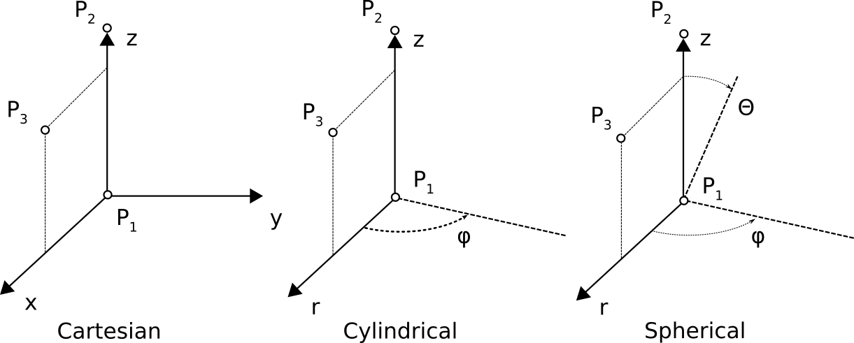
The Cartesian coordinate system transformation is defined as follows: The origin is equal to the point \(P_1\). The local z-axis is defined by \(z = P_2 - P_1\), the local y-axis by \((P_2 - P_2) \times P_3\), and the local x-axis \(x= ((P_2 - P_1) \times P_3) \times (P_2 - P_1)\).
The cylindrical coordinate system transformation is defined as follows: The origin is equal to the point \(P_1\). The cylinder z-axis is defined by \(z = P_2 - P_1\). The tangential (\(\phi\)) direction of a point \(P\) is then defined by \(t = (P -P_1) \times z\) and the cylinder’s radius direction \(r = z \times P_3\). Point \(P_3\), together with \(P_1\) and \(P_2\), spans a plane in which \(\phi=0\), rotating in the positive direction around the local z-axis \(z = P_2 - P_1\). Note: \(_3\) is ignored,i.e. the local \((r,\phi,z)\) system is uniquely defined by the node coordinate \(P\) and points \(P_1\) and \(P_2\).
The spherical coordinate system transformation is defined as
follows: The origin is equal to the point \(P_1\). The sphere
z-axis is defined by \(z = P_2 - P_1\). The tangential
(\(\phi\)) direction of a node \(P\) is then defined by
\(t = (`P - P_1) \times z\) and the sphere’s \(\theta\)
direction \(r = z \times P_3\). The declination \(\theta\)
rotates in a positive direction starting from z. Note: p3 is
ignored for transformation, i.e. the local \((\phi,\theta\),z)
system is uniquely defined by points \(P_1\) and \(P_2\).
Access
TRANSFORMATIONS is created by the input processor.
Validity
TRANSFORMATIONS is required if coordinate system transformations
are specified (see dataset NODA.branch).
Additional Information: Node transformations
Given the transformation definitions and the coordinates, the input processor computes the effective DOF transformation matrices for all nodes involved. The transformation matrices are stored in data sets NLCS.branch Node-local transformations and referred to by the second column of the NODA.branch sets. The transformation is defined as \(u_{nl} = T \cdot u_{bg}\), where \(u_{nl}\) is a vector referring to the node-local system and \(u_{bg}\) to the branch global system. The transformation \(T\) contains the 3 normalized base vectors \(e_i\) row-wise. \(e_i\) defines \(i^{th}\) base vector of the node-local system with respect to the branch-global system:
VOLUME.branch
Contains element volumes (MemCom relational table) of all elements of the branch.
Content of Dataset
Array table containing the volume of each element of the branch.
Access
VOLUME is created by the b2mass application.
Validity
Optional.