Generic Elements
B2000++ elements are always derived from one of the generic elements, i.e. an element of a specific family, like a triangle, a tetrahedron, etc. The generic element type is not associated to any operator and is usually known to all processors dealing with elements, like the input processor, the load processor, or the element processor. Like the generic element type, the element name must be derived from the generic element name. The element naming convention
sn.extension
has been adopted, where s designates the shape, n the number
of nodes defining the element, and extension the actual
description of the element, which also defines the operator. The table
below contains a list of all defined generic element types:
Name |
x |
Description |
|---|---|---|
Lx |
2, 3 |
Line or wire element. Generic 1D element, defined in R3. |
Rx |
2, 3 |
Rod element (solid mechanics) defined in R3. |
Bx |
2, 3 |
Beam element (solid mechanics) defined in R3. |
Tx |
3, 6 |
Triangular 2D element, defined in R2`or R:sup:`3. |
Qx |
4, 8, 9 |
Quadrilateral 2D element, defined in R2`or R:sup:`3. |
TEx |
4, 10 |
Tetrahedral element, defined in R3. |
HE |
8, 20, 27 |
Hexahedral element, defined in R3. |
PRx |
6, 15 |
Prismatic element, defined in R3. |
Note that if an element is listed in the above table this does not necessarily mean that the corresponding element - for a given operator - is implemented in B2000++.
The extension field defines the actual element type, i.e. the
operator, and can be chosen freely. Data set ELEMENT-PARAMETERS
contains the element name translation table.
Wire, Line (L) and Rod/Cable (R) Elements
L (line), R (rod and cable) elements define line (wire) elements without any local y- and z-axis, i.e. the elements have axisymmetric properties around the local x-axis. L elements also constitute the basis for axisymmetric two-dimensional elements.
The element local x-axis is defined by the vector \(p_{21} = p_2 - p_1\), with \(p_1\) being the coordinate vector of the vertex \(n_1\) and \(p_2\) the coordinate vector of the vertex \(n_2\). The local y- and z-axes are not defined. Note that B2000++ node indices are positive integers (external numbering system) and they must belong to the same branch.

Rod and cable element to node connectivities.
Beam (B) Elements
Beam elements refer to the beam local orthogonal coordinate system, the local x-axis being tangential to the beam axis, adn the local y-axis and z-axis in a plane normal to the x-axis. The orientation of the local y- and z-axes are defined:
by an orientation vector \(o\) defining the element local x-y plane with respect to the global coordinate system. The orientation vector must be specified by the MDL
elementsparameterbeam_orientation.by a mesh node \(n_{ref}\) which defines the beam orientation vector \(o = n_{ref} - n_{1}\), where \(n_{1}\) is the coordinate vector of the first node defining the beam element. Note that the node identification is external, see nodes command.
The node identifiers \(n_i\) are positive integers and all node iidentifiers defining the element must belong to the same branch (mesh).

Beam element-to-node connectivities and element local orientation.
Unless analytical integration is performed the standard Gauss scheme is used, for B2 element a 1 point scheme and for B3 elements a 2 point scheme.
Triangular (T, TR) Elements
T, TR elements define triangular elements in R2 and R3. B2000++ node identifiers \(n_i\) are positive integers and they must belong to the same branch. The element local x-axis xelement is defined by r21 = p2 - p1, with p2 being the coordinate of the vertex n2, and p1 the coordinate of the vertex n1. The element local z-axis zelement is defined by the vector product r21 . r31, with r31 = p3 - p1, and p3 being the coordinate of the vertex n3. The element local y-axis yelement is then obtained by the vector product zelement . xelement.

Element-to-node connectivities and element local orientations of triangular elements (left) and element edges (right).
Edge |
T3 element |
T6 element |
1 |
n1 n2 |
n1 n2 n4 |
2 |
n2 n3 |
n2 n3 n5 |
3 |
n3 n1 |
n3 n1 n6 |
All triangular elements requiring numerical integration have a built-in
default integration rule. The default integration rule can be changed
with the ischeme MDL element parameter.
Element |
Scheme |
Description |
|---|---|---|
T3 |
None |
3 point standard triangle integration scheme. |
T6 |
None |
7 point standard triangle integration scheme. |

Numerical integration scheme: Position and numbering of integration points.
Quadrilateral (Q) Elements
Q elements define quadrilateral elements in R2 and R3. B2000++ node identifiers \(n_i\) are positive integers and they must belong to the same branch. The element local x-axis xelement is defined by r21 = p2 - p1, with p2 being the coordinate of the vertex n2, and p1 the coordinate of the vertex n1. The element local z-axis zelement is defined by the vector product r21 . r31, with r31 = p3 - p1, and p3 being the coordinate of the vertex n3. The element local y-axis yelement is then obtained by the vector product zelement . x:element.

Element-to-node connectivities and element local orientations of quadrilateral elements (left) and element edges (right).
Edge |
Q4 element |
Q8/Q9 element |
1 |
n1 n2 |
n1 n2 n5 |
2 |
n2 n3 |
n2 n3 n6 |
3 |
n3 n4 |
n3 n4 n7 |
4 |
n4 n1 |
n4 n1 n8 |
Element |
Scheme |
Description |
|---|---|---|
Q4 |
None |
3 point standard 2x2 Gauss integration scheme. |
Q8, Q9 |
None |
9 point standard 3x3 Gauss integration scheme. |

Numerical integration scheme: Position and numbering of integration points.
Tetrahedral (TE) Elements
TE elements define tetrahedral elements in R3. B2000++ node identifiers \(n_i\) are positive integers and they must belong to the same branch. The element local x-axis xelement is defined by r21 = p:sub:2 - p1, with p2 being the coordinate of the vertex n2, and p1 the coordinate of the vertex n1. The element local z-axis zelement is defined by the vector product r21 . r31, with r31 = p3 - p1, and p3 being the coordinate of the vertex n3. The element local y-axis yelement is then obtained by the vector product zelement . x xelement.

Element-to-node connectivities and element local orientations of TE4 elements (left) and TE10 elements (right).

Element edges (left) and element faces (right).
Element face connectivity TE elements The element faces are numbered in counter-clockwise direction, as seen from outside the element. Thus, the element face normals (and the element face local z-axis) always point out from the element. The first 2 nodes of the element face connectivity list define the element face local x-axis xface. The element face local y-axis is defined by yface = r21 . r31, with r21 = p2 - p1 and r31 = p3 - p1, p1 being the coordinate of the element face connectivity node 1, p2 of node 2, and p3 of node 3. The element face local y-axis yface is then defined by zface . xface.
Face |
TE4 faces |
TE10 faces |
1 |
n1 n3 n2 |
n1 n3 n2 n7 n6 n5 |
2 |
n1 n2 n4 |
n1 n2 n4 n5 n9 n8 |
3 |
n2 n3 n4 |
n2 n3 n4 n6 n10 n9 |
4 |
n3 n1 n4 |
n3 n1 n4 n7 n8 n10 |
Element edge connectivity TE elements The element edge node connectivity of TE elements are defined as follows: The first 2 nodes of an element edge connectivity list also define the element edge local x-axis xedge, the axis running from the first to the second node. The figure and table below display the element local edge numbering, the orientation (direction) of the edge local x-axis, as well as the element nodes defining the edges.
Edge |
TE4 |
TE10 |
1 |
n1 n2 |
n1 n2 n5 |
2 |
n2 n3 |
n2 n3 n6 |
3 |
n3 n1 |
n3 n1 n7 |
4 |
n1 n4 |
n1 n4 n8 |
5 |
n2 n4 |
n2 n4 n9 |
6 |
n3 n4 |
n3 n4 n10 |
Element |
Scheme |
Description |
|---|---|---|
TE4 |
None |
3 point standard 2x2 Gauss integration scheme. |

Numerical integration scheme: Position and numbering of integration points.
Hexahedral (HE) Elements
HE elements define hexahedral elements in R3. B2000++ node identifiers \(n_i\) are positive integers and they must belong to the same branch. The element local x-axis xelement is defined by r21 = p2 - p1, with p2 being the coordinate of the vertex n2, and p1 the coordinate of the vertex n1. The element local z-axis zelement is defined by the vector product r21 . r31, with r31 = p3 - p1, and p3 being the coordinate of the vertex n3. The element local y-axis yelement is then obtained by the vector product zelement . x xelement.

Element-to-node connectivities and element local orientations of HE elements. Left: HE8 and HE20. Right: HE27 additional nodes.

Element edges (left) and element faces (right).
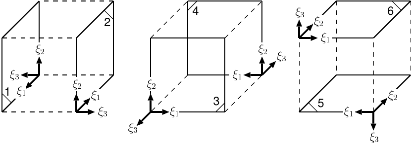
Element face local coordinate systems.
The element faces are numbered in counter-clockwise direction, as seen from outside the element. Thus, the element face normals (and the element face local z-axis) always point out from the element. The first 2 nodes of the element face connectivity list define the element face local x-axis xface. The element face local y-axis is defined by yface = r21 . r31, with r21 = p2 - p1 and r31 = p3 - p1, p1 being the coordinate of the element face connectivity node 1, p2 of node 2, and p3 of node 3. The element face local y-axis yface is then defined by zface . x xface.
Face |
HE8 |
HE20 |
HE27 |
1 |
n4 n1 n5 n8 |
n4 n1 n5 n8 n12 n17 n16 n20 |
n4 n1 n5 n8 n12 n17 n16 n20 n21 |
2 |
n2 n3 n7 n6 |
n2 n3 n7 n6 n10 n19 n14 n18 |
n2 n3 n7 n6 n10 n19 n14 n18 n22 |
3 |
n1 n2 n6 n5 |
n1 n2 n6 n5 n9 n18 n13 n17 |
n1 n2 n6 n5 n9 n18 n13 n17 n23 |
4 |
n3 n4 n8 n7 |
n3 n4 n8 n7 n11 n20 n1c5 n19 |
n3 n4 n8 n7 n11 n20 n15 n19 n24 |
5 |
n2 n1 n4 n3 |
n2 n1 n4 n3 n9 n12 n11 n10 |
n2 n1 n4 n3 n9 n12 n11 n10 n25 |
6 |
n5 n6 n7 n8 |
n5 n6 n7 n8 n13 n14 n15 n16 |
n5 n6 n7 n8 n13 n14 n15 n16 n26 |
Element edge connectivity HE elements The element edge node connectivity of HE elements are defined as follows: The first 2 nodes of an element edge connectivity list also define the element edge local x-axis xedge, the axis running from the first to the second node. The figure and table below display the element local edge numbering, the orientation (direction) of the edge local x-axis, as well as the element nodes defining the edges.
Edge |
HE8 |
HE20/HE27 |
1 |
n1 n2 |
n1 n2 n9 |
2 |
n2 n3 |
n2 n3 n10 |
3 |
n3 n4 |
n3 n4 n11 |
4 |
n4 n1 |
n4 n1 n12 |
5 |
n5 n6 |
n5 n6 n13 |
6 |
n6 n7 |
n6 n7 n14 |
7 |
n7 n8 |
n7 n8 n15 |
8 |
n8 n5 |
n8 n5 n16 |
9 |
n1 n5 |
n1 n5 n17 |
10 |
n2 n6 |
n2 n6 n18 |
11 |
n3 n7 |
n3 n7 n19 |
12 |
n4 n8 |
n4 n8 n20 |

Numerical integration scheme: Position and numbering of integration points.
Prismatic (PR) Elements
PR elements define prismatic elements in R3. B2000++ node identifiers \(n_i\) are positive integers and they must belong to the same branch. The element local x-axis xelement is defined by r21 = p2 - p1, with p2 being the coordinate of the vertex n2, and p1 the coordinate of the vertex n1. The element local z-axis zelement is defined by the vector product r21 . r31, with r31 = p3 - p1, and p3 being the coordinate of the vertex n3. The element local y-axis yelement is then obtained by the vector product zelement . x xelement.

Element-to-node connectivities and element local orientations of PR elements.
Element face connectivity PR elements The element faces are numbered in counter-clockwise direction, as seen from outside the element. Thus, the element face normals (and the element face local z-axis) always point out from the element. The first 2 nodes of the element face connectivity list define the element face local x-axis xface. The element face local y-axis is defined by yface = r21 . r31, with r21 = p2 - p1 and r31 = p3 - p1, p1 being the coordinate of the element face connectivity node 1, p2 of node 2, and p3 of node 3. The element face local y-axis yface is then defined by zface . x xface.
1 |
n1 n3 n2 |
n1 n3 n2 n9 n8 n7 |
2 |
n4 n5 n6 |
n4 n5 n6 n10 n11 n12 |
3 |
n1 n2 n5 n4 |
n1 n2 n5 n4 n7 n14 n10 n13 |
4 |
n2 n3 n6 n5 |
n2 n3 n6 n5 n8 n15 n11 n14 |
5 |
n3 n1 n4 n6 |
n3 n1 n4 n6 n9 n13 n12 n15 |
Element edge connectivity PR elements The element edge node connectivity of PR elements are defined as follows: The first 2 nodes of an element edge connectivity list also define the element edge local x-axis xedge, the axis running from the first to the second node. The figure and table below display the element local edge numbering, the orientation (direction) of the edge local x-axis, as well as the element nodes defining the edges.
Edge |
PR6 |
PR15 |
1 |
n1 n2 |
n1 n2 n7 |
2 |
n2 n3 |
n2 n3 n8 |
3 |
n3 n1 |
n3 n1 n9 |
4 |
n4 n5 |
n4 n5 n10 |
5 |
n5 n6 |
n5 n6 n11 |
6 |
n6 n4 |
n6 n4 n12 |
7 |
n1 n4 |
n1 n4 n13 |
8 |
n2 n5 |
n2 n5 n14 |
Edge 9: |
n3 n6 |
n3 n6 n15 |
Point Mass (PMASS) Element
The PMASS element adds mass at a given grid point with respect to the element-local axes. Note that B2000++ node identifiers \(n_i\) are positive integers and they must belong to the same branch.

Point mass element connectivity and local coordinate system.
Rigid Body (RBE) Elements
The RBE element connects a master node to one or several slave nodes.