Element Components
Element components in B2000++ calculate the first variation and the second variation of the potential associated to the specific element. They also generate mass matrices, damping matrices, and field integration over the elements. Note that the latter are evaluated, if required, in the deformed state!
The first variation is basically a vector containing, in the case of displacement-based solid mechanics FE equations, the equilibrium forces of an element.
The second variation is basically a matrix linking, again in the case of displacement-based solid mechanics FE equations, the displacements to the forces of an element.
The mass matrices and damping matrices are matrices linking, again in the case of displacement-based solid mechanics FE equations, the accelerations and velocities to the forces of an element.
The reader is referred to text books, such as the text book by [Bathe96].
Element components also include the element properties that are
assigned to each element via the ElementProperty classes
defined in the b2element_property_xxx files. Each element object
has an associated element property object containing pointers to
PROPERTY.pid and MATERIAL.mid objects. Th element object itself
contains data and functions for computing variations and field
integration. The ElementProperty classes for beam elements
creates a property object
ElementPropertyper property It gets the PROPERTY.pid dict (RTableobject).creates material properties, etc. of the element.
Optional, MASS, MASS_CENTER, MASS_INERTIA_MOMENTS, NON_STRUCTURAL_MASS, NON_STRUCTURAL_MASS_CENTER are read from PROPERTY.pid.
To implement a user-written element the following code and code modifications must be provided:
In the input processor: The element parameters of the new element must be specified (see Input Processor).
- In the solver: By providing a new element class or by copying and
modifying an existing class.
The implementation of one of the simplest elements - the (non-linear)
rod and cable element -by means of an example is explained in the
following sections. The example is found in the b2programming
package under components/rod_element.

Input Processor
All elements processed by b2ip++ must provide a minimum amount of information which describes the basic properties of an element. This information is provided by the database table ELEMENT-PARAMETERS. This table must be generated in b2ip++. Generating the table in the code (instead of providing a configuration file or something similar) has the advantage that the table is always up to date.
Keyword |
Type |
Description |
|---|---|---|
|
int |
Set to 1 if the element is a candidate to |
|
int |
Internal element number of this element. |
|
int |
Length of temperature array. |
|
string |
Element name. |
|
int |
Array containing the node type numbers of all element nodes as defined by NODE-PARAMETERS. |
The input processor always starts with creating the Epars object
(see src/ip/b2ip_epar.H). Epars then defines the built-in
element parameters by calling
ip/b2ip_epar_insert_builtin.C, which contains hard-coded element
parameters for all built-in
elements. ip/b2ip_epar_insert_builtin.C defines each element
parameters set with (from b2programming example):
Epar& epar = insert("R2.S");                 // Element name
epar.ntypes.insert(epar.ntypes.end(), 2, 1); // Node types (=1)
epar.ltemp = 1;                              // How many temperatures at node
epar.needs_mid = true;  // b2ip++ specific for checkling input
epar.needs_area = true; // b2ip++ specific for checkling input
The epar.needs rules are defined in src/ip/b2ip_epar.H.
The user-defined element is not in the built-in list and must be added by the user by providing a function that will be dynamically loaded and executed (from b2programming example):
#include "ip/b2ip_epar.H"

namespace b2000::ip {

extern "C" void register_user_defined_epars(Epars& epars)
{
    //Add the element parameter block of a user-defined element. Dataset
    //ELEMENT-PARAMETERS will then contain the new definition.

    std::cerr << "***INFO: Add element parameters for 'R2.S.USER'." << std::endl;
    {
        epar.ntypes.insert(epar.ntypes.end(), 2, 1); // Node types (here: all=1)
        epar.ltemp = 1;                              // How many temperatures at node
        epar.needs_mid = true;                       // Required mid (b2ip++ only)
        epar.needs_area = true;                      // Required area (b2ip++ only)
    }
}

}
b2ip++ will load all built-in element parameters and then search in
the library path for a shared library “libb2000.element.R2.S.USER” and
execute the function register_user_defined_epars()
Element Implementation
This section explains how to program a b2element class. For
this purpose one of the simplest typical solid mechanics elements - the
standard non-linear 2 node rod and cable element - is presented. The
relevant project (C++ code, cmake files, test cases) are found in
the b2programming package under
components/rod_element
Check with the README.rst file.
Implementations of elements, element material properties, boundary
conditions, solvers, etc. are all sub-classes of b2000::Object.
Instances of b2000::ObjectType are factory objects which create
instances of specific sub-classes of b2000::Object and which, in
conjunction with b2000::Module, allow for the implementation of
plugins without having to recompile B2000++. b2000::Object and
b2000::ObjectType are explained in chapter Components.
Hence, elements, as is the case of all other objects, are registered in the object factory, i.e the element must be made known to the solver.
The role of the element class is to compute the variations with respect to the DOFs. This
Provide initialization functions for defining element attributes required by the computation of the variations with respect to the DOFs and for initializing the element property object for this element. These functions are called once during a run by the
Domainobject when creating the object.Provide the get_value() function.
Global Element Program Structure
We now explain the blocks of the element C++ code that pertain to the implementation of the element.

Objects involved in rod element class.
The global program structure is listed below. It shows the template class and the implementation class blocks:
// Set test printout verbose level
#define VERBOSE 0

#include ...

namespace b2000 {

    // Template class ElementRodUser declaration for all shapes (R2,
    // R3, R4. Here: Only R2 element implemented).

    template<typename SHAPE, typename INTEGRATION, int nb_gauss>
    //=================================================
    class ElementRodUser: public TypedElement<double>
    //=================================================
    {
    public:
        // See below ""Public Template Class Declarations""
    private:
        Node* nodes[SHAPE::num_nodes]; // The node identifiers
        SolidMechanicsRod<double>* property; // The property object
        typedef SolidMechanicsRod<double>* property_list_t;
        property_list_t* property_list;
        double non_structural_mass;
      };

    // Declaration of the object *type*. The name "R2.S.USER" will be used
    // to identify the object.
    template<>
    ElementRodUser<L2_Shape_Evaluator, IS_L, 2>::type_t
    ElementRodUser<L2_Shape_Evaluator, IS_L, 2>::type("R2.S.USER", "",
             StringList(), b2000::element::module,
             &b2000::TypedElement<double>::type);

    // ElementRodUser class for 2 node shapes
    template class ElementRodUser<L2_Shape_Evaluator, IS_L, 2>;

    // Implementation of the 1st and 2nd variation
    template<typename SHAPE, typename INTEGRATION, int nb_gauss>
    void ElementRodUser<SHAPE, INTEGRATION, nb_gauss>::get_value()
    { // see below }

    // Implementation of the body force integrator.
    template<typename SHAPE, typename INTEGRATION, int nb_gauss>
    void ElementRodUser<SHAPE, INTEGRATION, nb_gauss>::field_volume_integration(...)
    { // see below }

    // Implementation of the element edge load integrator.
    template<typename SHAPE, typename INTEGRATION, int nb_gauss>
    void ElementRodUser<SHAPE, INTEGRATION, nb_gauss>::field_edge_integration(...)
    { // see below }

} // end namespace B2000
Public Template Class Declarations
The public declarations of the template class include the
constructor and destructor and the templatized methods.
Start with specifying the node types node_type. Node types help to
identify compatible elements.
// The node types. The rod element nodes are identified by
// 3 coordinates X, Y, Z and 3 displacements DX, DY, DZ.
typedef node::HNode<
coordof::Coor<coordof::Trans<coordof::X, coordof::Y, coordof::Z> >,
coordof::Dof<coordof::DTrans<coordof::DX, coordof::DY, coordof::DZ> > >
node_type;
Object constructor and destructor:
// Constructor: Initialize properties of element
ElementRodUser()
    : property(0), property_list(0), non_structural_mass(0) {}

// Destructor: Delete properties
~ElementRodUser() {
    if (property_list) {
        for (int g = 0; g != nb_gauss; ++g)
            delete property_list[g];
        delete[] property_list;
    }
}
The get_nodes function
The get_nodes() function returns the number of nodes and the
nodes defining the element. The values are defined by the current
SHAPE object.
std::pair<int, Node* const *> get_nodes() const {
    return std::pair<int, Node* const *>(SHAPE::num_nodes, nodes);
}
The set_nodes function
The set_nodes() sets the internal node identifiers nodes of
the element. set_nodes() is called by the Domain
object when creating the element.
void set_nodes(std::pair<int, Node* const *> nodes_) {
    if (nodes_.first != SHAPE::num_nodes)
        Exception() << "This element must have " << SHAPE::num_nodes << " nodes." << THROW;
    for (int i = 0; i != SHAPE::num_nodes; ++i)
        nodes[i] = nodes_.second[i];
}
The get_property function
The get_property() function returns the element material
property object.
const ElementProperty* get_property() const {
    return property;
}
The set_property function
The set_property() sets the element material
property. set_property() is called by the Domain object
when creating the element.
void set_property(ElementProperty* property_) {
    // Get the property (material): The element property object
    // for rod elements is defined in
    // elements/properties/b2solid_mechanics.H and derives from
    // ElementProperty which derives from model/b2element.H
     property = dynamic_cast<SolidMechanicsRod<double>*> (property_);
    if (property == 0)
        TypeError() << "Bad or missing element property for rod/cable "
            "element " << get_object_name() << " (forgot MID or PID "
            "element attribute?) " << THROW;
    if (property->path_dependent()) {
        if (property_list) {
            for (int g = 0; g != nb_gauss; ++g)
                delete property_list[g];
            delete[] property_list;
        }
        property_list = new property_list_t[nb_gauss];
        for (int g = 0; g != nb_gauss; ++g)
            property_list[g] = dynamic_cast<SolidMechanicsRod<double>*>(property->copy());
    }
}
set_additional_properties() allows for extracting additional
element material properties.
void
set_additional_properties(const RTable& rtable) {
    non_structural_mass = rtable.get_double("NON_STRUCTURAL_MASS", 0);
}

const std::vector<VariableInfo> get_value_info() const {
    return std::vector<VariableInfo>(3, Element::nonlinear);
}
The get_value function
The get_value() function is called by the solver for computing
the derivatives of the DOFs, such as the first and second variation and
gradients.
void get_value(
    // The model object to which the element belongs (input).
    Model& model,

    // Flag to indicate if the value returned must be linear in
    // function of the dof and the time derivative of the dof (input).
    const bool linear,

    // If true, the given dof and time derivatives represent an
    // equilibrium solution (input). Used by the elements with
    // path dependent materials only.
    const EquilibriumSolution equilibrium_solution,

    // The current time (input).
    const double time,

    // The current time step of the incremental solution solver
    // (input).
    const double delta_time,

    // The values and the time derivatives of all DOFs present
    // in the FE model. The first column of the matrix *dof[0]*
    // are the DOFs. The i-th column of the matrix, i.e *dof[i]*
    // is the i-th time derivative of *dof[0]* (matrix, input).
    const linalg::Matrix<double, linalg::Mrectangle_constref>& dof,

    // Storage of gradient data computed by the Element and/or
    // ElementProperty object (output).
    GradientContainer* gradient_container,

    // Can be used to add hints for the Solver, such as damage
    // material models, fracture elements, etc. (output).
    SolverHints* solver_hints,

    // Array of the global DOF indices on which the internal
    // forces (first variation)  depend (vector, output).
    linalg::Index& dof_numbering,

    // The first variation (or internal forces) as a function of
    // DOFs and time (vector, output).
    linalg::Vector<double, linalg::Vdense>& value,

    // A vector of bool indicating for which derivatives of
    // *dof* the second variation should be computed (input).
    const std::vector<bool>& d_value_d_dof_flags,

    // The second variation: *d_value_d_dof[i]* contains the
    // derivatives of *dof[i]*. If *d_value_d_dof[i].is_null()*,
    // then the matrix shall not be computed (vector of packed
    // matrices, output).
    std::vector<linalg::Matrix<double, linalg::Mpacked> >& d_value_d_dof,

    // The derivatives of *value* with respect to time (vector,
    // output).

    linalg::Vector<double, linalg::Vdense>& d_value_d_time)
The field_volume_integration function
The field_volume_integration() method is called if a field has
to be integrated over the element volume, such as gravity loads:
void field_volume_integration(
    const linalg::Vector<double, linalg::Vdense_constref>& dof,
    const linalg::Vector<double, linalg::Vdense_constref>& dofdot,
    const linalg::Vector<double, linalg::Vdense_constref>& dofdotdot,
    const Field<double>& field,
    linalg::Index& dof_numbering,
    linalg::Vector<double, linalg::Vdense>& discretised_field,
    linalg::Matrix<double, linalg::Mpacked>& d_discretised_field_d_dof);
The field_edge_integration function
The field_edge_integration() method is called if a field has to
be integrated over an element edge, such as line loads:
void field_edge_integration(
    const linalg::Vector<double, linalg::Vdense_constref>& dof,
    const linalg::Vector<double, linalg::Vdense_constref>& dofdot,
    const linalg::Vector<double, linalg::Vdense_constref>& dofdotdot,
    const Field<double>& field,
    int edge,
    linalg::Index& dof_numbering,
    linalg::Vector<double, linalg::Vdense>& discretised_field,
    linalg::Matrix<double, linalg::Mpacked>& d_discretised_field_d_dof);
Finally, the type declaration for the object factory. The static
variable type
using type_t = ObjectTypeComplete<ElementRodUser,
TypedElement<double>::type_t>;

static type_t type;
Implementation of get_value
This is the actual code that computes the element first and second variation. See The get_value function for an explanation of the arguments.
template<typename SHAPE, typename INTEGRATION, int nb_gauss>
void ElementRodUser<SHAPE, INTEGRATION, nb_gauss>::get_value(

    b2000::Model& model,
    const bool linear,
    const EquilibriumSolution equilibrium_solution,
    const double time,
    const double delta_time,
    const b2000::linalg::Matrix<double, b2000::linalg::Mrectangle_constref>& dof,
    b2000::GradientContainer* gradient_container,
    SolverHints* solver_hints,
    linalg::Index& dof_numbering,
    b2000::linalg::Vector<double, b2000::linalg::Vdense>& value,
    const std::vector<bool>& d_value_d_dof_flags,
    std::vector<b2000::linalg::Matrix<double, linalg::Mpacked> >& d_value_d_dof,
    b2000::linalg::Vector<double, b2000::linalg::Vdense>& d_value_d_time)
{
#if VERBOSE > 0
    //
    std::cout << "Element " << get_object_name() << " Start get_value time=" << time << " deltat=" << delta_time << std::endl;
#endif

    bool compute_d_value_d_dof;
    bool compute_d_value_d_dofdotdot;

    // value (1st var) always computed
    if (!value.is_null()) {
        value.resize(SHAPE::num_nodes * 3);
        value.set_zero();
    }

    if (d_value_d_dof_flags.size() != 0 && d_value_d_dof_flags[0]) {
#if VERBOSE > 0
        std::cout << "    d_value_d_dof_flags[0]: var2 requested" << std::endl;
#endif
        compute_d_value_d_dof = true;
        d_value_d_dof[0].resize(SHAPE::num_nodes * 3, true);
        d_value_d_dof[0].set_zero();
    } else
        compute_d_value_d_dof = false;

    if (d_value_d_dof_flags.size() > 1 && d_value_d_dof_flags[1]) {
#if VERBOSE > 0
        std::cout << "   d_value_d_dof_flags[1] requested" << std::endl;
#endif
        d_value_d_dof[1].resize(SHAPE::num_nodes * 3, true);
        d_value_d_dof[1].set_zero();
    }

    if (d_value_d_dof_flags.size() > 2 && d_value_d_dof_flags[2]) {
#if VERBOSE > 0
        std::cout << "   d_value_d_dof_flags[2] set: dofdotdot requested" << std::endl;
#endif
        compute_d_value_d_dofdotdot = true;
        d_value_d_dof[2].resize(SHAPE::num_nodes * 3, true);
        d_value_d_dof[2].set_zero();
    } else
        compute_d_value_d_dofdotdot = false;

    if (!d_value_d_time.is_null()) {
#if VERBOSE > 0
        std::cout << "   value_d_time requested" << std::endl;
#endif
        d_value_d_time.resize(SHAPE::num_nodes * 3);
        d_value_d_time.set_zero();
    }

    dof_numbering.resize(SHAPE::num_nodes * 3);
    {
        size_t* ptr = &dof_numbering[0];
        for (int k = 0; k != SHAPE::num_nodes; ++k)
            ptr = node_type::get_global_dof_numbering_s(ptr, nodes[k]);
    }
#if VERBOSE > 1
    std::cout << "   DOF numbering:";
    for (const auto &d : dof_numbering) std::cout << " " << d;
    std::cout << std::endl;
#endif

    // Get the nodes coordinate
    double node_coor[SHAPE::num_nodes][3];
    for (int k = 0; k != SHAPE::num_nodes; ++k)
        node_type::get_coor_s(node_coor[k], nodes[k]);

    INTEGRATION integration;
    //integration.set_scheme(1);
    integration.set_num(nb_gauss);
    if (nb_gauss != integration.get_num())
        Exception() << "Cannot find an integration scheme with "
        << nb_gauss << " integration points." << THROW;

    // iteration on gauss point
    for (int ng = 0; ng != nb_gauss; ++ng) {
#if VERBOSE > 1
        std::cout << "   Integrate gauss point " << ng << std::endl;;
#endif

        double icoor;
        double weight;
        double N[SHAPE::num_nodes];
        double dN[SHAPE::num_nodes][1];
        {
            integration.get_point(ng, icoor, weight);
            SHAPE::eval_h(&icoor, N);
            SHAPE::eval_h_derived(&icoor, dN);
        }

        double dx0[3] = {}; // derivative of the undeformed rod axis
        double du[3] = {}; // derivative of the deformed rod axis
        if (dof.is_null() || dof.size2() == 0)
            for (int k = 0; k != SHAPE::num_nodes; ++k)
                for (int i = 0; i != 3; ++i)
                    dx0[i] += dN[k][0] * node_coor[k][i];
        else
            for (int k = 0; k != SHAPE::num_nodes; ++k)
                for (int i = 0; i != 3; ++i) {
                    dx0[i] += dN[k][0] * node_coor[k][i];
                    du[i] += dN[k][0] * dof(dof_numbering[k * 3 + i], 0);
                }

        const double dx0_2 = dx0[0] * dx0[0] + dx0[1] * dx0[1] + dx0[2] * dx0[2];
        const double inv_dx0_2 = 1 / dx0_2;
        weight *= std::sqrt(dx0_2);

        // pk2 strain in the axis of the deformed rod
        double epsxx = 0;
        for (int i = 0; i != 3; ++i)
            epsxx += dx0[i] * du[i];
        if (!linear)
            for (int i = 0; i != 3; ++i)
                epsxx += 0.5 * du[i] * du[i];
        epsxx *= inv_dx0_2;

        double velocity[3] = {};
        if (dof.size2() > 1)
            for (int k = 0; k != SHAPE::num_nodes; ++k)
                for (int i = 0; i != 3; ++i)
                    velocity[i] += N[k] * dof(dof_numbering[k * 3 + i], 1);

        double acceleration[3] = {};
        if (dof.size2() > 2)
            for (int k = 0; k != SHAPE::num_nodes; ++k)
                for (int i = 0; i != 3; ++i)
                    acceleration[i] += N[k] * dof(dof_numbering[k * 3 + i], 2);

        if (gradient_container) {
            // Compute and store the integration point coordinates.
            const GradientContainer::InternalElementPosition ip = {icoor, 0, 0};
            gradient_container->set_current_position(ip, weight *
                (property_list ? property_list[ng] : property)->get_area());
            static const GradientContainer::FieldDescription coor_descr = {
                "COOR_IP",
                "x.y.z",
                "Coordinate of the point",
                3, 3, 1, 3, false, typeid(double)
            };
            if (gradient_container->compute_field_value(coor_descr.name)) {
                double coor[3] = {};
                for (int k = 0; k != SHAPE::num_nodes; ++k)
                    for (int i = 0; i != 3; ++i)
                        coor[i] += N[k] * node_coor[k][i];
                gradient_container->set_field_value(coor_descr, coor);
            }

            // Compute and store the displacement at the integration
            // point coordinate.s
            static const GradientContainer::FieldDescription disp_descr = {
                "DISP_IP",
                "dx.dy.dz",
                "Displacement at the point",
                3, 3, 1, 3, false, typeid(double)
            };
            if (gradient_container->compute_field_value(disp_descr.name)) {
                double disp[3] = {};
                for (int k = 0; k != SHAPE::num_nodes; ++k)
                    for (int i = 0; i != 3; ++i)
                        disp[i] += N[k] * dof(dof_numbering[k * 3 + i], 0);
                gradient_container->set_field_value(disp_descr, disp);
            }
        }

        double Fx; // Fx (sigxx integrated over section)
        double C; // dFx/depsxx (integrated over section)
        double inertial_force[3];
        double density; // in mass/length

        // Call the element property function get_stress.  get_stress
        // computes rod and cable forces Fx (sxx*area)

        /*********************************************************/
        (property_list ? property_list[ng] : property)->get_stress(
        /*********************************************************/
            &model,
            linear,
            equilibrium_solution,
            time,
            delta_time,
            gradient_container,
            solver_hints,
            this,
            Vector<double, Vdense_constref>(SHAPE::num_nodes, N),
            dx0,
            du,
            epsxx,
            velocity,
            acceleration,
            Fx,
            C,
            inertial_force,
            density);

        // Compute the derivatives of the strains wrt to the dofs (if
        // applicable).
        if (!value.is_null() || compute_d_value_d_dof) {
#if VERBOSE > 0
            std::cout << "      Compute derivatives d_eps/d_DOF" << std::endl;
#endif
            double B[SHAPE::num_nodes * 3];
            if (linear || dof.is_null() || dof.size2() == 0)
                for (int k = 0; k != SHAPE::num_nodes; ++k)
                    for (int i = 0; i != 3; ++i)
                        B[k * 3 + i] = inv_dx0_2 * dx0[i] * dN[k][0];
            else
                for (int k = 0; k != SHAPE::num_nodes; ++k)
                    for (int i = 0; i != 3; ++i)
                        B[k * 3 + i] = inv_dx0_2 * (dx0[i] + du[i]) * dN[k][0];

            if (!value.is_null()) {
                {
                    const double s = weight * Fx;
                    for (int i = 0; i != 3 * SHAPE::num_nodes; ++i)
                        value[i] += s * B[i];
                }
                // Add inertial forces.
                if (dof.size2() > 2)
                    for (int i = 0; i != 3; ++i) {
                        const double s = weight * (
                            inertial_force[i] +
                            acceleration[i] * non_structural_mass);
                        for (int k = 0; k != SHAPE::num_nodes; ++k)
                            value[k * 3 + i] += s * N[k];
                    }
            }

            if (compute_d_value_d_dof) {
                {
                    const double s = weight * C;
                    double* ptr = &d_value_d_dof[0](0, 0);
                    for (int j = 0; j != 3 * SHAPE::num_nodes; ++j)
                        for (int i = 0; i <= j; ++i, ++ptr)
                            *ptr += s * B[i] * B[j];
                }
                if (!linear && Fx != 0) {
                    const double s = weight * Fx * inv_dx0_2;
                    for (int kj = 0; kj != SHAPE::num_nodes; ++kj)
                        for (int ki = 0; ki <= kj; ++ki) {
                            const double s1 = s * dN[ki][0] * dN[kj][0];
                            for (int i = 0; i != 3; ++i)
                                d_value_d_dof[0](ki * 3 + i, kj * 3 + i) += s1;
                        }
                }
            }

        }

        // Compute the derivatives of the strains wrt to time (if
        // applicable).
        if (compute_d_value_d_dofdotdot) {
            const double s = weight * (density + non_structural_mass);
            for (int kj = 0; kj != SHAPE::num_nodes; ++kj)
                for (int ki = 0; ki <= kj; ++ki) {
                    const double s1 = s * N[ki] * N[kj];
                    for (int i = 0; i != 3; ++i)
                        d_value_d_dof[2](ki * 3 + i, kj * 3 + i) += s1;
                }
        }
    }
}
Implementation of field_volume_integration
This is the actual code that computes, in the case of the rod element, the element body forces (if defined by nbc body loads).
// Implementation of the body force integrator.
template<typename SHAPE, typename INTEGRATION, int nb_gauss>
void ElementRodUser<SHAPE, INTEGRATION, nb_gauss>::field_volume_integration(
    const linalg::Vector<double, linalg::Vdense_constref>& dof,
    const linalg::Vector<double, linalg::Vdense_constref>& dofdot,
    const linalg::Vector<double, linalg::Vdense_constref>& dofdotdot,
    const Field<double>& field,
    linalg::Index& dof_numbering,
    linalg::Vector<double, linalg::Vdense>& discretised_field,
    linalg::Matrix<double, linalg::Mpacked>& d_discretised_field_d_dof) {

    if (discretised_field.is_null())
        return;

    // Set the dof numbering scheme.
    dof_numbering.resize(SHAPE::num_nodes * 3);
    {
        size_t* ptr = &dof_numbering[0];
        for (int k = 0; k != SHAPE::num_nodes; ++k)
            ptr = node_type::get_global_dof_numbering_s(ptr, nodes[k]);
    }

    // Expand and initialize vector of concentrated forces.
    discretised_field.resize(dof_numbering.size());
    discretised_field.set_zero();

    // Get the node coordinates in the undeformed and deformed
    // configuration.
    double node_coor_0[SHAPE::num_nodes][3];
    for (int k = 0; k != SHAPE::num_nodes; ++k)
        node_type::get_coor_s(node_coor_0[k], nodes[k]);
    double node_coor_d[SHAPE::num_nodes][3];
    copy_array(node_coor_0, node_coor_d);
    if (!dof.is_null() && dof.size() > 0)
        for (int k = 0; k != SHAPE::num_nodes; ++k)
            for (int j = 0; j != 3; ++j)
                node_coor_d[k][j] += dof[dof_numbering[3 * k + j]];

    INTEGRATION integration;
    integration.set_num(nb_gauss);
    if (nb_gauss != integration.get_num())
        Exception() << "Cannot find an integration scheme for "
        << nb_gauss << " integration points." << THROW;

    const double area = property->get_area();

    // Iterate over Gauss points and sum up integral contributions.
    for (int ng = 0; ng != nb_gauss; ++ng) {
        double weight;
        double N[SHAPE::num_nodes];
        double dN[SHAPE::num_nodes][1];
        double lcoor;
        {
            integration.get_point(ng, lcoor, weight);
            SHAPE::eval_h(&lcoor, N);
            SHAPE::eval_h_derived(&lcoor, dN);
        }

        double coor_0[3] = {};
        double coor_d[3] = {};
        double dx0[3] = {}; // Derivative of the undeformed rod axis
        double dxd[3] = {}; // Derivative of the deformed rod axis
        for (int k = 0; k != SHAPE::num_nodes; ++k)
            for (int i = 0; i != 3; ++i) {
                coor_0[i] += N[k] * node_coor_0[k][i];
                coor_d[i] += N[k] * node_coor_d[k][i];
                dx0[i] += dN[k][0] * node_coor_0[k][i];
                dxd[i] += dN[k][0] * node_coor_d[k][i];
            }

        const double dx0_2 = dx0[0] * dx0[0] + dx0[1] * dx0[1] + dx0[2] * dx0[2];
        weight *= std::sqrt(dx0_2);

        // Evaluate.
        linalg::Vector<double, linalg::Vdense> value;
        field.get_value(
            linalg::Vector<double, linalg::Vdense_constref>(3, &lcoor),
            linalg::Vector<double, linalg::Vdense_constref>(3, coor_0),
            linalg::Vector<double, linalg::Vdense_constref>(3, coor_d),
            linalg::Matrix<double, linalg::Mrectangle_constref>(3, 3, dx0),
            linalg::Matrix<double, linalg::Mrectangle_constref>(3, 3, dxd),
            value);
        if (value.size() != 3)
            UnimplementedError() << THROW;
        double mult = 1;
        double add = 0;
        if (field.get_multiply_with_density()) {
            mult = property->get_density(); // in mass/length^3
            add = non_structural_mass;
        }

        for (int k = 0; k != SHAPE::num_nodes; ++k)
            for (int j = 0; j != 3; ++j)
                discretised_field[k * 3 + j] +=
                    N[k] * weight * (value[j] * area * mult + add);
    }
}
Implementation of field_edge_integration
This is the actual code that computes, in the case of the rod/cable element, the element edge loads (if defined by nbc edge loads).
// Implementation of the element edge load integrator.
template<typename SHAPE, typename INTEGRATION, int nb_gauss>
void ElementRodUser<SHAPE, INTEGRATION, nb_gauss>::field_edge_integration(
        const linalg::Vector<double, linalg::Vdense_constref>& dof,
        const linalg::Vector<double, linalg::Vdense_constref>& dofdot,
        const linalg::Vector<double, linalg::Vdense_constref>& dofdotdot,
        const Field<double>& field,
        int edge,
        linalg::Index& dof_numbering,
        linalg::Vector<double, linalg::Vdense>& discretised_field,
        linalg::Matrix<double, linalg::Mpacked>& d_discretised_field_d_dof) {
    if (discretised_field.is_null())
        return;

    // Set the dof numbering scheme.
    dof_numbering.resize(SHAPE::num_nodes * 3);
    {
        size_t* ptr = &dof_numbering[0];
        for (int k = 0; k != SHAPE::num_nodes; ++k)
            ptr = node_type::get_global_dof_numbering_s(ptr, nodes[k]);
    }

    // Expand and initialize vector of concentrated forces.
    discretised_field.resize(dof_numbering.size());
    discretised_field.set_zero();

    // Get the node coordinates in the undeformed and deformed
    // configuration.
    double node_coor_0[SHAPE::num_nodes][3];
    for (int k = 0; k != SHAPE::num_nodes; ++k)
        node_type::get_coor_s(node_coor_0[k], nodes[k]);
    double node_coor_d[SHAPE::num_nodes][3];
    copy_array(node_coor_0, node_coor_d);
    if (!dof.is_null() && dof.size() > 0)
        for (int k = 0; k != SHAPE::num_nodes; ++k)
            for (int j = 0; j != 3; ++j)
                node_coor_d[k][j] += dof[dof_numbering[3 * k + j]];

    INTEGRATION integration;
    integration.set_num(nb_gauss);
    if (nb_gauss != integration.get_num())
        Exception() << "No integration scheme found that contains "
        << nb_gauss << " integration points." << THROW;

    // Iterate over Gauss points and sum up integral contributions.
    for (int ng = 0; ng != nb_gauss; ++ng) {
        double weight;
        double N[SHAPE::num_nodes];
        double dN[SHAPE::num_nodes][1];
        double lcoor;
        {
            integration.get_point(ng, lcoor, weight);
            SHAPE::eval_h(&lcoor, N);
            SHAPE::eval_h_derived(&lcoor, dN);
        }

        double coor_0[3] = {};
        double coor_d[3] = {};
        double dx0[3] = {}; // Derivative of the undeformed rod axis
        double dxd[3] = {}; // Derivative of the deformed rod axis
        for (int k = 0; k != SHAPE::num_nodes; ++k)
            for (int i = 0; i != 3; ++i) {
                coor_0[i] += N[k] * node_coor_0[k][i];
                coor_d[i] += N[k] * node_coor_d[k][i];
                dx0[i] += dN[k][0] * node_coor_0[k][i];
                dxd[i] += dN[k][0] * node_coor_d[k][i];
            }

        const double dx0_2 = dx0[0] * dx0[0] + dx0[1] * dx0[1] + dx0[2] * dx0[2];
        weight *= std::sqrt(dx0_2);

        // Evaluate.
        linalg::Vector<double, linalg::Vdense> value;
        field.get_value(
            linalg::Vector<double, linalg::Vdense_constref>(3, &lcoor),
            linalg::Vector<double, linalg::Vdense_constref>(3, coor_0),
            linalg::Vector<double, linalg::Vdense_constref>(3, coor_d),
            linalg::Matrix<double, linalg::Mrectangle_constref>(3, 3, dx0),
            linalg::Matrix<double, linalg::Mrectangle_constref>(3, 3, dxd),
            value);
        if (value.size() != 3)
            UnimplementedError() << THROW;

        for (int k = 0; k != SHAPE::num_nodes; ++k)
            for (int j = 0; j != 3; ++j)
                discretised_field[k * 3 + j] += weight * N[k] * value[j];
    }
}
Build the Element Project
The user element project is built with the cmake build system. The output of the build process is the shared library
<CMAKE_INSTALL_PREFIX>/lib/libb2000.element.R2.S.USER.so
To build the project, go to the components/rod_element
directory, and
cd <b2programming>/components/rod_element
mkdir -p build
cd build
cnake [-DCMAKE_INSTALL_PREFIX=$SMR_PREFIX] ..
make install

...
The example cmake user written element project found in the
b2programming package under directory
components/rod_property is set up as follows:
rod_element: CMakeLists.txt

rod_element/src: b2element_rod_user.C, CMakeLists.txt,register_user_defined_epars.C

rod_element/test: rod45user, truss
The root cmake file:file:rod_element/CMakeList.txt:
#[[
Main cmake file to build user-defined element
=============================================

Example configuration with default $SMR_PREFIX and $SMR_CMAKEMODULE defined:

   mkdir _build; cd _build; cmake ..; make install

Note: The target "make install" must be executed.

Options to cmake:

   -DCMAKE_INSTALL_PREFIX=<path-to-install-prefix>
   -DCMAKE_MODULE_PATH=<path-to-cmodules>

Author: S. R. P. Merazzi, SMR SA

]]

cmake_minimum_required(VERSION 3.19)
project(rod DESCRIPTION "user-defined rod element" VERSION 1.0.0 LANGUAGES CXX)

include("../common.cmake")

add_subdirectory(src)
The cmake build file rod_element/src/CMakeList.txt for
building the libary:
# cmake file to generate B2000++ make file for user-written rod element
# =====================================================================

.. code-block:: none

   # Authors: Silvio Merazzi, SMR SA, Thomas Rothermel, DLR

   # Create a shared library for the new R2.S.USER element. It will be
   # loaded dynamically by B2000++ solver if a R2.S.USER element is
   # found. Compile and add b2element_cable_user.C.

   add_library(b2000.element.R2.S.USER SHARED "")

   # Compile and add to library
   target_sources(b2000.element.R2.S.USER
       PRIVATE
           register_user_defined_epars.C
           b2element_rod_user.C
   )

   # Link library with B2000 and Python3 libaries
   target_link_libraries(b2000.element.R2.S.USER
       PUBLIC B2000::B2000
       PUBLIC Python3::Python
   )

   # Installs the user element library.
   Install(
       TARGETS b2000.element.R2.S.USER LIBRARY
       DESTINATION ${CMAKE_INSTALL_LIBDIR}
   )
To build the project, create a build directory, such as
rod_element/_build and (if SMR_PREFIX is defined):
cd rod_element/_build
cmake -DCMAKE_INSTALL_PREFIX=$SMR_PREFIX ..
make install
Testing the Element
If the build is successful, select one of the system tests found under
rod_component/test.
Test Case “rod45”
Example with two rods loaded in compression by a force. The problem is a pure 2D problem, with all DOFs except Ux and Uy removed. The test is geometrically linear.
Rod FE model.
Note that the test is executed with the built-in element (-define
ELTYPE=R2.S on the command line) or with the user written element
R2.S.USER (-define ELTYPE=R2.S.USER on the command line). To run
the test with the user written element R2.S.USER you have to build the
rod_element project.
The following load cases are defined:
Case 1 (default): Force Fy on node 2.
Case 2: Inertia load in -y direction (tests body loads).
Case 3: Thermal expansion.
Execute with user defined element ‘R2.S.USER’ and print displacements of node 2:
b2000++ -define ELTYPE=R2.S rod.mdl
b2print_solutions rod.b2m

b2000++ -define ELTYPE=R2.S.USER rod.mdl
*** Invalid element type 'R2.S.USER', or parameters for element type
    are not defined, looking for a user element.
*** Found library containing user element 'R2.S.USER'.
***INFO: Add element parameters for 'R2.S.USER'.
*** Element 'R2.S.USER' registered.
and print solutions with the b2print_solutions application:
b2print_solutions --case=1 rod.b2m

DOF field DISP, branch=1, case=1  cycle=0, nodeset="all nodes"
 EID  Ux       Uy  Uz
   1   0        0   0
   2   0 -0.01408   0
   3   0        0   0

b2print_solutions --case=2 rod.b2m

DOF field DISP, branch=1, case=2  cycle=0, nodeset="all nodes"
EID  Ux         Uy  Uz
  1   0          0   0
  2   0 -3.731e-06   0
  3   0          0   0

b2print_solutions --case=3 rod.b2m

DOF field DISP, branch=1, case=3  cycle=0, nodeset="all nodes"
 EID  Ux      Uy  Uz
   1   0       0   0
   2   0 0.00297   0
   3   0       0   0
To clean up directory:
make clean
As an exercise, create an __init__.py file for the unit test
environment B2000++ System Tests.
Test Case “rod10”
The rod10 test is similar to the rod45 test, the h over B ratio being smaller in order to provoke a ‘snap-through’ (see figure below). The geometrically non-linear analysis steered by the hyper-plane incremental control type in order to overcome singularities along the path. The problem is a pure 2D problem, with all DOFs except Ux and Uy removed.

Note that the test is executed with user written element R2.S.USER. To run the test you have to build the rod_element project.
This variant of rod45 exhibits the snap-through when loaded.
Execute with built-in element:
b2000++ rod.mdl
To generate the graphs displayed below, enter:
python3 make_graphs.py

Test Case “truss”
This test is the same as the one found under
$B2VERIFICATION/verification/converters/bdf/bdf_truss
To run the test with the user-defined rod element (after having
converted the BDF file to MDL), replace the string R2.S with R2.S.USER
(see Makefile):
sed -e 's/R2.S/R2.S.USER/' truss.mdl > a.mdl; mv a.mdl truss.mdl
The file:Makefile default target converts the file, replaces the element name, and runs the case:
make
To obtains the defomed shape plot:
baspl++ bv-deformed.py
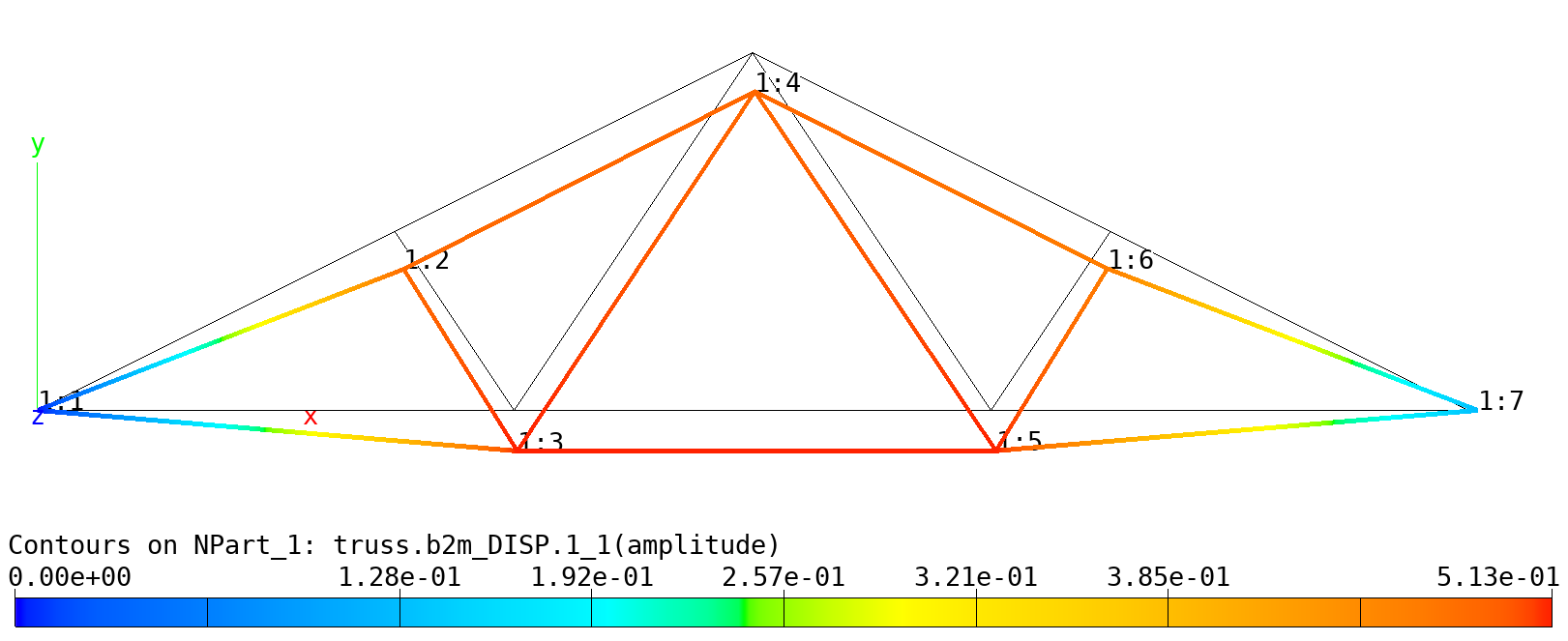
Truss: Deformed shape.