6. Basic System Tests
6.1. Beam Element Tests
6.1.1. Thermal Expansion of Beam
Folder: $B2VERIFICATION/basic/beams/beam45
This test is similar to the static snap test and the b2propramming rod test, but with beams instead of rods.
6.1.2. Beam with Spring Support
Folder: $B2VERIFICATION/basic/beams/elastic_support
The model consist of a clamped beam with a spring support in the global y-direction at the right free end. The beam is loaded by a line load in the global y-direction along the whole span.
Beam mesh: Beam elements (red), spring (blue).
The spring is modeled either by a SPRING element or by an
equivalent R2.S rod element. The equivalence between the spring
stiffness \(k\) and the rod element properties \(A\) and
\(l\) is
where \(k\) is the spring stiffness and \(A\) the equivalent rod cross section are and \(l\) equivalent rod length, the elastic modulus \(E\) being the same for both models.
Dimensions and material parameters, and the load can be found in the
MDL input file cantilever.mdl.
The dimensions, material parameters, and the load can be found in the respective MDL input files.
Three cases are defined:
Beam with spring element (
atype="spring"). The dof Uy of the spring element at node 11 is attached to dof UY of node 12, which itself is constrained with UX=UY=UZ=0.
Beam with spring element (
atype="springg"). The dof Uy of the spring element at node 11 is attached to the ‘ground’.Beam with equivalent rod element (
atype="rod"). The rod element spans from node 11 to node 12 in y-direction, and the node 12 is constrained with Ux=Uy=Uz=0.
The deformations with both model are exactly the same. The figure below shows the deformed shape.

Beam with elastic support: Deformed shape (blue), initial shape (black). Scale factor of deformation: 500.
In case of a beam with spring element (atype="spring"), where dof
Uy of the spring element at node 11 is attached to dof UY of node 12,
the element table dictionary on the database is
EID = [2]
ENDRELEASE1 = [0]
ENDRELEASE2 = [0]
ENDRELEASE_STABILISE = [0.]
ITYP = [151]
MBASE = [31.  0.  1.  0.]
MID = [0]
NODES = [2 3]
PID = [100]
In case of a beam with spring element (atype="springg"), where dof
Uy of the spring element at node 11 is attached to the ‘ground’, the
element table dictionary on the database is
EID = [2]
ENDRELEASE1 = [0]
ENDRELEASE2 = [0]
ENDRELEASE_STABILISE = [0.]
ITYP = [151]
MBASE = [31.  0.  1.  0.]
MID = [0]
NODES = [2 3]
PID = [100]
6.1.3. Beam End Release Tests
Folder: $B2VERIFICATION/basic/beams/endrelease
The beam end release capability is tested with small plane beam structures made of steel tubes. Both the rod (R2.S) and beam elements (B2.S.RS) are tested. For details about the models, see MDL input files
The MDL file truss1.mdl tests the truss structure with rod
(R2.S) elements, and truss2.mdl the truss structure with beam
(B2.S.RS) elements, adding end releases to all elements. All DOF’s
except 1 and 2 are suppressed. The shear correction factors must be
set to 0.0 The resulting deformed shape (deformations amplified) and
the applied force are displayed below:
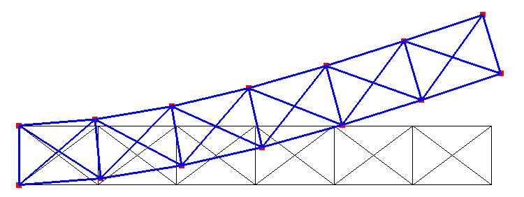
Beam end release tests: Deformed truss shape.
The MDL file frame.mdl tests a frame structure with beam
(B2.S.RS) elements and a single end release of the top of the middle
column, where it is attached to the horizontal beam.
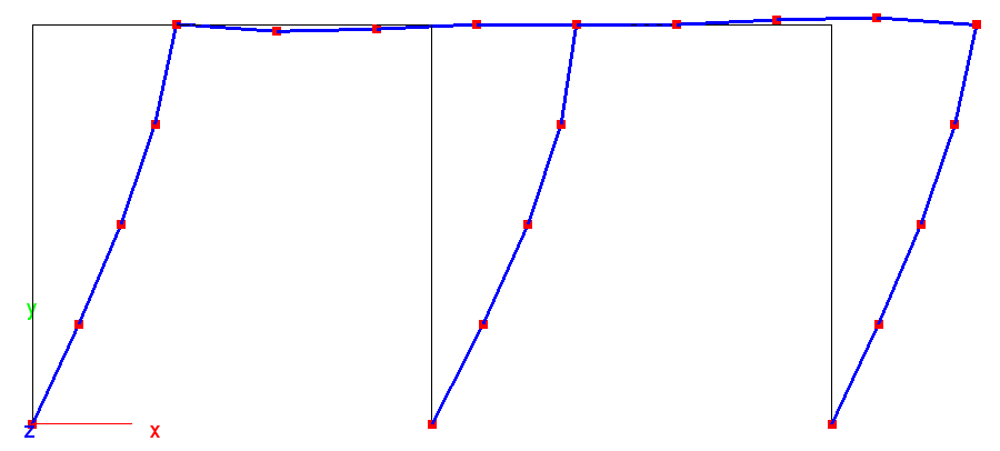
Beam end release tests: Deformed frame shape.
6.1.4. Beam with pin-joint
Folder: $B2VERIFICATION/basic/beams/gerbertraeger
The model consist of a beam that spans over 2 segments (see figure below). The first segment of the beam is supported at both ends. The right end of the second segment reflects symmetry. A pin-joint is placed such that the beam becomes ‘statically determinate’, preferably at a place where the moment is 0 for the dominating load case. The principle is called after the German engineer H. G. Gerber who designed bridges in the 19th century.
Beam with pin-joint: Mesh and supports.
The dimensions, material parameters, and the load can be found in the respective MDL input files.
Two models are defined:
End-releases at one element attached to the pin-joint (
releases.mdl).Duplicated nodes at the pin-joint location. The nodes are coupled with linear constrains, except for the rotation \(R_{z}\), thus modeling the pin-joint (
linc.mdl).

Beam with pin-joint: Deformed beam shape (amplified).
The deformations with or without pin-joint are quite close. This is to be expected, because the pin-joint is near the place where \(M_{zz}=0\) in the system without pin-joint. Note that this is the general idea with the Gerbertraeger: Place the pin joint where the moment for the main load case, usually the weight, is 0 in a system without pin-joint. The table below shows the displacement \(D_{z}=0\) under the load P:
Item |
Release |
Linc |
|---|---|---|
DZ Symmetry |
-0.1102 |
-0.1102 |
Reaction Force A |
-150 |
-150 |
Reaction force Fz at B |
650 |
650 |
Moment My at B |
-3500 |
-3500 |
The moment \(M_{zz}\) and the stress \(\sigma_{xx}\) along the beam (end release model) are plotted in the figure below. At the location of the pin joint (x=13) the moment must be 0 for both elements attached to the node at x=13.
Moment \(M_{zz}\) along beam x-axis. Results identical for both models.
Moment \(M_{zz}\) along beam x-axis. Results identical for both models.
Failure index (von Mises) along beam x-axis. models.
The moments, stresses, and failure index graphs were obtained with the
script plot_moments_stresses.py. Stresses can be printed with
the script stresses.py.
6.1.5. Beam Element Offset Tests
Folder: $B2VERIFICATION/basic/beams/offset
The beam offset tests check the beam elements eccentricities (offsets) on a straight thin clamped beam modeled by Bx.S.RS elements and loaded by an axial load with an beam eccentricity either in the (branch) global y-axis (0.0, 1.0, 0.0) or the (branch) global z-axis (0.0, 0.0, 1.0). Note that the beam eccentricity vector is defined in the (branch) global coordinate system. The global and the beam local coordinate systems coincide for the global tests, except for the local tests with the beam local y-axis rotated by 90 degrees around the global x-axis.
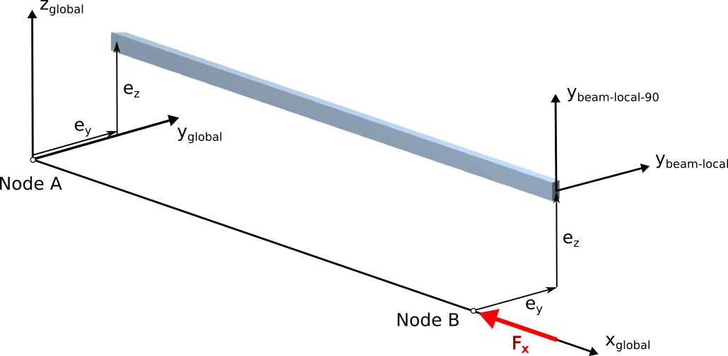
Beam offset test: Coordinate systems.
For the eccentricity ey, Fx creates a negative moment My=-ey*Fx around the y axis, leading to a negative displacement along y.
For the eccentricity ez, Fx creates a negative moment Mz=-ez*Fx around the z axis, leading to a negative displacement along z.
The same tests are then performed with a beam-local orientation (see figure above) by rotating the beam orientation axis by 90 degrees around the beam x-axis.
Some tests are performed with the beam section properties solver. The mesh of the beam section property solver being displayed below:
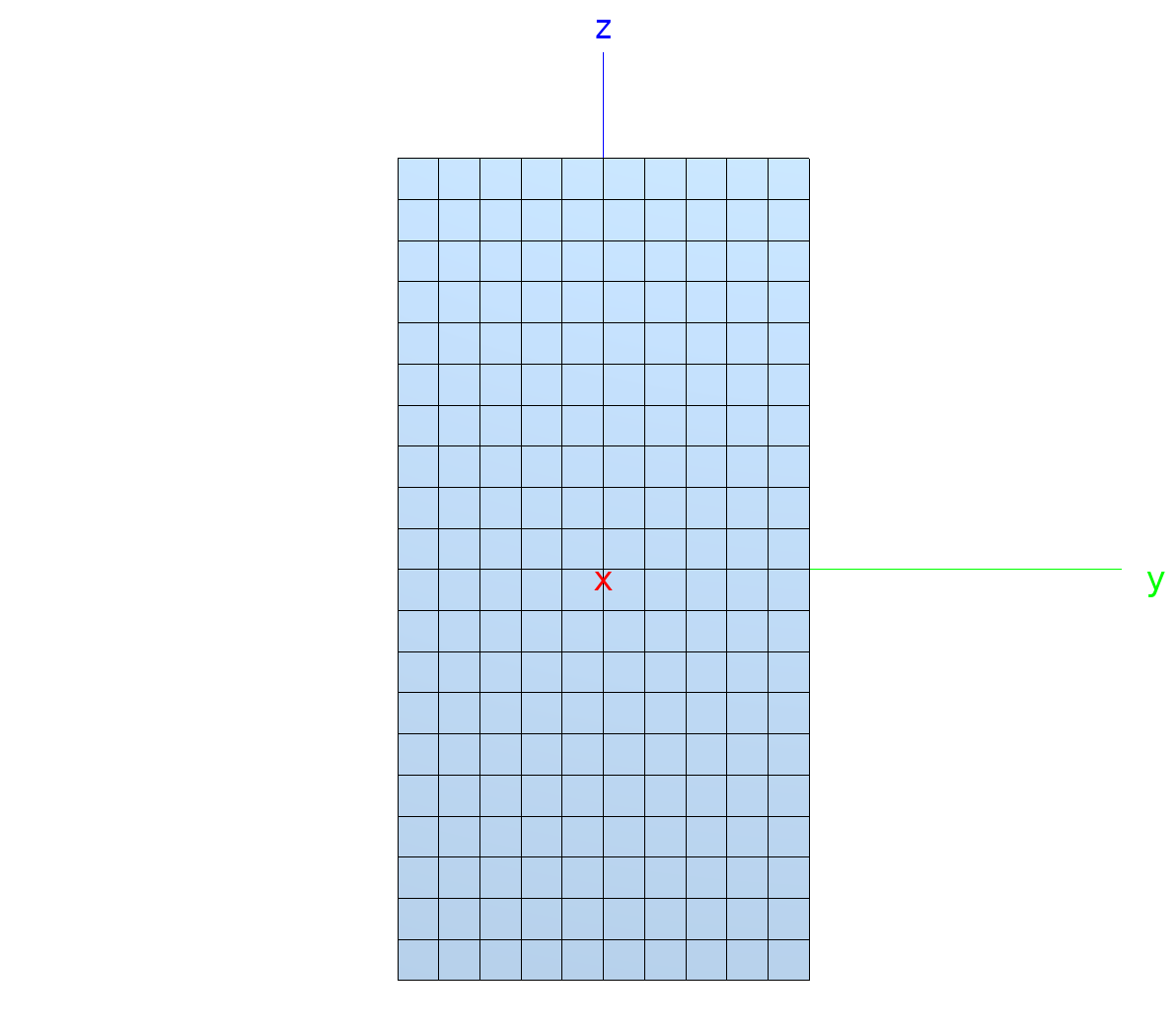
Beam offset test: Section solver mesh.
6.1.6. Beam Section Properties Tests
Folder: $B2VERIFICATION/basic/beams/sections
These tests check beam elements section properties with a simple beam
model. The MDL input files are generated by a Python scripts, see file
__init__.py. Results are compared to analytical solutions.
6.1.7. Beam Strain and Stress Tests
Folder: $B2VERIFICATION/basic/beams/strains_and_stresses
These tests check rod and beam strain and stresses generated with simple models, comparing results to available analytical ones
4_beams_in_line.mdltests strains and stresses of a row of beam elements loaded with prescribed displacements (ebc).4_rods_in_line.mdltests strains and stresses of a row of rod elements.:file:
cantilever3.mdl` tests strains and stresses in a cantilever
beam, comparing results to analytical ones. The length L of the
cantilever must be much larger than the height or width, such that
shear deformations are negligible. Beam properties are defined with
the ``property
MDL beam property specification.single_rod_element.mdltests strains and stresses of a single rod element.
6.2. Constraint Tests
6.2.1. Constraint Tests (RBE, LINC, FMDE, JOIN)
folder: $B2VERIFICATION/basic/constraints
These tests check the functioning of special constraints in B2000++ (neither EBC nor NBC):
RBE: Rigid body elements.
LINC: Linear constraint equations linking node DOF’s.
FMDE: Force-moment distribution elements, a variant of RBE’s for non-linear analysis.
JOIN (link nodes): Tests node to node and DOF to DOF connections as well as automatic detection of node to node connections.
Shell tests are specifically designed for B2000++ and the 5 DOF MITC
shell elements: Except if both nodes have a similar normal, the solver
automatically assigns 6 DOF nodes for nodes linked with join.
DOF to DOF coupling with linear constraints check the linear
constraint equation capabilities with the linc command. The test
couples 2 independent meshes with a linear constraint equations. Each
structure consists of a cantilever beam modeled with beam elements. A
single equation is defined, linking the v-displacement of the tip node
a cantilever beam 1 (branch 1) to the v-displacement of the tip node b
of cantilever beam 2 (branch 2). Thus, the equation is of the form va = vb or, va - vb = 0
In the MDL language, the above equation is specified as follows, considering that DOF 2 of the beam mid-node (node 55 of branch 11) is linked to DOF 2 of node 11 of branch 22 (a node with the same coordinates as node 55 of branch 11):
linc
   equation 2 0.0 11 55 2 1.0 22 11 2 -1.0
end
MDL file |
|
Test case size |
Small |
The solution is equal to the one obtained with beam element rotation end
releases set accordingly: One beam element attached to the beam model
mid-node must remove rotations (see MDL element option
node_rot_dofs in MDL file beam1.mdl). The deformed shape is
displayed below:
6.3. Hyperelasticity Tests
6.3.1. Solid 3 Element Tests
Folder: $B2VERIFICATION/basic/hyperelastic/hexahedral
These basic hyperelasticity tests comprise the following test cases for different hyperelastic material implementations:
Tension and compression tests (“simple tension test”)
Equibiaxial deformation tests for both tension and compression
Pure shear test
Simple shear test
6.3.2. Membrane 3 Element Tests
Folder: $B2VERIFICATION/basic/hyperelastic/quadrilateral
These basic hyperelasticity tests comprise the following test cases for different hyperelastic material implementations:
Tension and compression tests (“simple tension test”)
Equibiaxial deformation tests for both tension and compression
Pure shear test
Simple shear test
6.4. Invariance Tests
6.4.1. Invariance to Node Shift Tests
Note
Location of verification case:
verification/basic/invariance/node_shifts
These tests check the invariance to a node shift for T3, Q4, Q8, and Q9 MITC shell elements and for TE and HE solid elements.
6.4.2. Invariance to Mesh Rotation/Translation Tests
Note
Location of verification case:
verification/basic/invariance/rotation
These tests check if models are invariant to arbitrary rotations and translations in space. Solid mechanics and heat analysis elements are tested. The tests work as follows:
Generate a B2000 model database with the B2000++ input processor.
Rotate all components of the database: Coordinates, boundary conditions, etc.
Make an analysis and check the results. Results must be identical to the ones obtained with the original database.
6.5. Laminate Test
Folder: $B2VERIFICATION/basic/laminates
This tests case check the laminate integration and stress computation of the MITC shell elements. Gradients (strains and stresses) are calculated for each layer individually, independent of the number of integration points specified, with gradients computed at the lower surface, the mid-point, and at the upper surface of each layer.
6.5.1. Laminated plate stacking tests
Folder: $B2VERIFICATION/basic/laminates/bending
The model is a rectangular plate defined in the x-y plane and modeled with 4 elements in the x-direction and 3 elements in the y-direction, with the plate being clamped on the left edge and loaded in the x-direction on the right edge.
Plate model
Out-of plane displacements and in-plane rotations are locked. The following test input options can be set:
matid: Material id number: matid=1 refers to the laminate definition, matid=2 is the material data used by the laminate, and matid=13 refers to the equivalent isotropic material definition, as the laminate is quasi-isotropic (90/0/+45/-45).elemtype: elemtype=4 selects the Q4.S.MITC.E4 shell element. elemtype=8 selects the Q8.S.MITC shell element. elemtype=9 selects the Q9.S.MITC shell element.
Displacements for the different through-thickness integration methods for the laminate as well as the isotropic material model must give identical results for the same element type. The stresses are independent of the through-thickness laminate integration method used. No stresses are checked for the isotropic material model. There are some slight differences between the 4-node and 9-node element results, as is to be expected. The tables below list the results checked for the 4-node and 9-node elements:
Result |
Position |
Value |
|---|---|---|
Axial displacement (Ux) |
Tip (x=8.7, y=0) |
0.074029 |
Side compression (Uy) |
Root |
0.0036125 |
Axial stress (Sxx) |
Element 8, integration point 3, layer 1 |
92.1 |
Axial stress (Sxx) |
Element 8, integration point 3, layer 2 |
1255 |
Axial stress (Sxx) |
Element 8, integration point 3, layer 3 |
312 |
Axial stress (Sxx) |
Element 8, integration point 3, layer 4 |
317 |
6.5.2. Laminated plate bending test
Folder: $B2VERIFICATION/basic/laminates/membrane
This test checks the bending behavior of the MITC shell elements. The modeled problem is a rectangular plate under a sinusoidal load. The edges of the plates are simply supported. In order to exploit the symmetry of the considered problem only a quarter of the plate is modeled. The B2000++ solution is validated with the analytic solution according to Reddy [reddy]. Therefore, the transverse displacement in the z-direction is compared at the point (0, 0, 0), where the deflection is maximal. The analytic solution is only valid for orthotropic laminates. Two different laminates are tested.
Layer |
Thickness |
Angle |
1 |
0.02 |
0 |
2 |
0.04 |
90 |
3 |
0.02 |
0 |
Layer |
Thickness |
Angle |
1 |
0.02 |
0 |
2 |
0.02 |
90 |
3 |
0.02 |
0 |
4 |
0.02 |
90 |
6.6. Loads and Boundary Conditions
6.6.1. Inertia Loads
Location of verification case: $VERIFICATION/basic/loads/inertia_loads
These tests check the generation of inertia loads. Inertia loads in B2000++ are specified by means of the accelerations boundary condition type of the MDL nbc (natural boundary conditions) command and assigned in the tests1 to case 2.
The tests compute the loads (FORCE datasets) generated by mass and acceleration and compare the sum to the required sum.
Mass is generated either with density and element volume or with non structural mass.
truss.mdl: Simple truss made of R2.S rods.beam45.mdl: This test is similar to the static snap test and the b2propramming rod test, but with beams instead of rods. Tests Bx.S.RS elements.beam.mdl: Clamped beam (tests Bx.S.RS elements).plate.mdl: Rectangular plate. Tests Qx.S, Tx.S shell elements.solid.mdl: Cube testing all sold elements.
6.6.2. Traction Loads
Note
Location of verification case:
verification/basic/bc/tractions
These tests check the generation of traction loads. Traction loads are loads generated on surfaces, such as shell surfaces or solid element faces.
6.7. Mass and Volume
6.7.1. Mass and Center-of-Gravity Tests
Note
Location of verification case:
verification/basic/mass_and_cog
These tests check the computation of mass of a model and the determination of the center-of-gravity (COG). The tests launch b2mass. Elements contributing to the mass of a structure, i.e. structural 1D, 2D, and 3D elements as well as mass elements are tested.
6.7.2. Non-Structural Mass Tests
Folder: $BEVERIFICATION/basic/mass/nsm
Tests the non-structural mass option of B2000++ together with free vibration analysis of rod, beam, and shell element models. The tests are run with
Density only.
Non-structural mass only.
Both density and non structural mass.
The non-structural mass is computed such that specifying non-structural mass only gives the same result as specifying density only:
For rod and beam elements nsm=density*area.
For shell elements nsm=density*thickness.
Values can be consulted in the test file __init__.py and in the
input files.
6.8. Model Description language (MDL) Tests
Location of verification case: $B2VERIFICATION/basic/md
The Model Description language (MDL) tests check basic features of the
B2000 input processor commands. Additional documentation of the test
cases can be found in the MDL input files and the __init__.py
files of the relevant directories.
bc: Tests MDL nbc and ebc blocks and checks the content of the generated EBC and NBC datasets.
cases: Tests mdl case blocks.
material: Tests the MDL material and properties blocks and checks the relevant generated sets on the database.
epatch: Tests element patch generation and checks the relevant generated sets on the database.
groups: Tests element groups and panels definition.
morientation: Check the various methods of specifying material orientations of the morientation and mbase blocks.
nbc_ebc: Tests to generate natural boundary conditionms, such as line loads and surface tractions, pressure. Verification is done with checking analysis results, not with checking generated forces (TODO).
sets: Tests node and element set definition blocks and checks the relevant generated sets on the database.
Note
The tests are not exhaustive!
6.9. Shear Deformation Tests
Note
Location of verification case:
verification/basic/shear_deformation
These tests check shear stresses produced by Q shell and HE solid
elements. See also comment in __init__.py.
6.10. Shell Element Test
6.10.1. Membrane and bending patch test
Folder: $B2VERIFICATION/basic/shells/bending_patch_test
The standard displacement-controlled shell element bending patch test checks whether the elements can exactly reproduce an out-of plane stress state for any configuration. Quadrilateral and triangular shell elements of first and second order. are tested.
6.10.2. Stresses in Shells (Cantilever)
Folder: $B2VERIFICATION/basic/shells/cantilever
This test computes displacements and stresses of a simple cantilever beam modeled with Q shell elements. The purpose of this test is (1) to obtain stresses of Q4 and Q9 elements that can be compared to analytical values and (2) to illustrate how stresses are calculated in shells.
The beam is modeled by 5+1 or 10+1 elements, where the single element at the clamped edge is very small and serves to obtain stresses close to the clamped edge. An equally distributed pressure load in the z-direction is applied.
To obtain results that can be compared to the simple analytical Euler beam solution, the Poisson ratio has been set to 0.
A sampling point plot with baspl++ displays the stress in the global x-direction at the sampling points at the shell top layer (left edge is clamped):

Examining the stresses of element 1 with the browser for the 5 element case and Q4 elements show a good agreement with the analytical stress (+-7.5e+06).
Sample field STRESS ("Stresses in solids and shells (Cauchy Stresses)")

Element Point     Sxx
      1     1   -7.425e+06 top layer
      1     2   -7.425e+06 top layer
      1     3   -7.425e+06 top layer
      1     4   -7.425e+06 top layer
      1     5     6.36e-11 middle layer
      1     6     6.79e-11 middle layer
      1     7    3.803e-11 middle layer
      1     8    4.233e-11 middle layer
      1     9    7.425e+06 bottom layer
      1    10    7.425e+06 bottom layer
      1    11    7.425e+06 bottom layer
      1    12    7.425e+06 bottom layer
Note that shell elements store stresses in stress layers (top, middle, bottom) through the shell thickness.
Result are extracted and graphs produced with the q4.py and
q9.py scripts.
Item |
Q4 5 el. |
Q4 10 el. |
Q9 5 el. |
Q9 10 el. |
|---|---|---|---|---|
Tip DZ [mm] |
0.8931 |
0.8931 |
0.8931 |
0.8931 |
Sxx [MPa] |
7.425 |
7.425 |
7.48 |
7.48 |
Stresses Sxx along x with 5 Q4 elements. Black lines: Distribution in the element (2 points -1,+1 in element coordinates r). Black dot: Mean value. Red: Analytical (Euler beam).
Stresses Sxx along x with 10 Q4 elements. Black lines: Distribution in the element (2 points -1,+1 in element coordinates r). Black dot: Mean value. Red: Analytical (Euler beam).
Stresses Sxx along x with 5 Q9 elements. Black lines: Distribution in the element (3 points -1,0,+1 in element coordinates r). Black dot: Mean value. Red: Analytical (Euler beam).
Stresses Sxx along x with 5 Q9 elements. Black lines: Distribution in the element (3 points -1,0,+1 in element coordinates r). Black dot: Mean value. Red: Analytical (Euler beam).
6.10.3. Shell 1 element test 1
Folder: $B2VERIFICATION/basic/shells/case1
A single rectangular linear shell element with a length of 3.78 in the x-direction, 4.27 in the y-direction and a thickness of 0.132 is subject to four different loading conditions: Axial loading in x-direction, axial loading in xy-direction, bending around the x-axis, and bending around the y-axis.
The results are compared to the analytical solutions listed below. The test is performed for 4, 8, and 9 node Q shell elements. The in-plane loading conditions are also applied to 2D elements (plane-stress).
sigma_xx |
0.9332 |
delta_x |
0.885324 |
sigma_yy |
1.138 |
delta_y |
1.22131 |
sigma_yy_1 |
0.02988 |
sigma_yy_3 |
0.008007 |
delta_z |
0.876609 |
theta_x |
0.30794 |
sigma_xx_1 |
0.02342 |
sigma_xx_3 |
0.006274 |
delta_z |
0.538346 |
theta_y |
-0.213629 |
6.10.4. Membrane patch test
Folder: $B2VERIFICATION/basic/shells/case2
The standard displacement-controlled membrane patch test checks whether the elements can exactly reproduce a constant in-plane strain state for any configuration. If this is the case, then the element will converge to the mathematically exact solution (assuming that the materials are elastic and deformations are small), as the mesh is refined. However, depending on the element type and problem, convergence may be too slow for practical purposes.
The displacement field is described by the following bi-linear equations:
ux = ax0 + ax1 x + ax2 y
uy = ay0 + ay1 x + ay2 y
where axiand ayi are set by the user. All constants should be non-zero. The above displacements are prescribed on all boundary nodes of the patch. The displacement of the internal nodes and the strains and stresses inside the elements are to be obtained with a linear static analysis. The displacements of the internal nodes should follow the same displacement field.
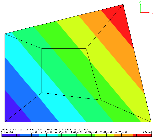
Membrane patch test: Patch geometry and displacement field
Node |
X |
Y |
Z |
1 |
0.0 |
0.0 |
0.0 |
2 |
9.9 |
0.0 |
0.0 |
3 |
8.0 |
8.0 |
0.0 |
4 |
0.0 |
6.0 |
0.0 |
5 |
2.5 |
2.0 |
0.0 |
6 |
6.5 |
1.5 |
0.0 |
7 |
5.5 |
5.0 |
0.0 |
8 |
2.5 |
5.0 |
0.0 |
ax0 |
0.0001 |
ax1 |
0.0061 |
ax2 |
0.0049 |
ay0 |
-0.0005 |
ay1 |
0.0042 |
ay2 |
0.0038 |
The analytical solution for the strains are obtained by deriving the expressions of the displacement field with respect to x and y:
εxx = ax1
εyy = ay2
εxy = ax2 + ay1
The test case supports quadrilateral and triangular shell and 2D elements of first and second order.
6.10.5. Shell 1 Element Test 5
Folder: $B2VERIFICATION/basic/shells/case5
This test is based on Example 6.6 of the in the textbook by K.J. Bathe [bathe1996]. A rectangular plate with edges of length 2 is stretched in-plane at the upper right corner with a displacement of (1., 0.5), as shown in the figure below:
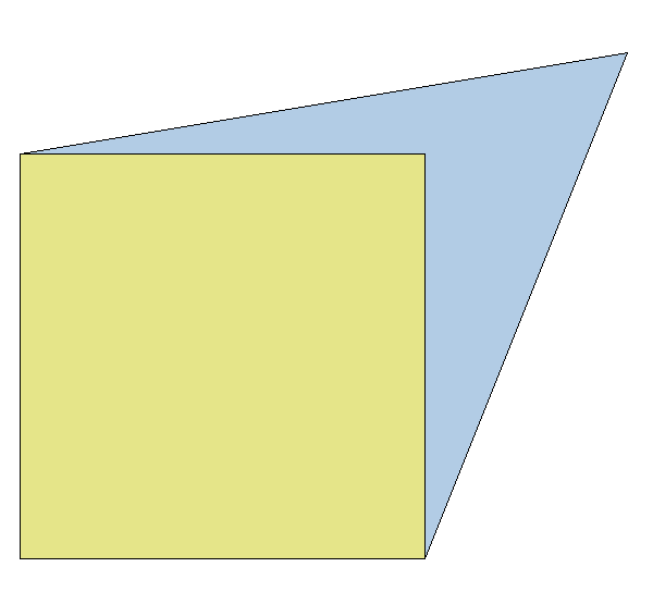
Shell 1 Element Test 5: Initial and deformed shape
The test checks the linear and non-linear in-plane behavior of quadrilateral shell and 2D elements (plane-stress conditions). The strains and the stresses are compared to the analytical solution for the linear case. For the nonlinear case, the Green-Lagrange strains and the Cauchy stresses are separately computed by the test and compared to the strains and stresses obtained from the FE analysis.
For elements having internal degrees-of-freedom, those degrees-of-freedom are locked in this test. Otherwise, the interpolated FE strains and stresses will not correspond to those computed by the test.
6.10.6. Shell 1 Element Test (eccentricity)
Folder: $B2VERIFICATION/basic/shells/eccentricities
The test checks the Q element shell eccentricity feature with a one element test.
6.10.7. One Element Test with Large Strain
Folder: B2VERIFICATION/basic/shells/nonlinear_stress
The test checks the Q element shell large in-plane Cauchy stresses with a 1 element test.
6.10.8. One Element Test with Plane Strain Condition
Folder: B2VERIFICATION/basic/shells/plane_strain
This test checks the plane strain element material, for a single simple mechanical load case pulling the element at one end while retained at the other end such that lateral deformation is enabled. The test compares the computed out-of-plane stress with the analytical one.
6.11. Solid Elements
6.11.1. Anisotropic Solid Material Test
Folder: $B2VERIFICATION/basic/solids/anisotropic
The test checks if specification of an anisotropic material gives the same result as if an isotropic material is specified.
The test case consists of a cantilever beam modeled by 8 node hexahedral continuum elements. The beam is loaded by an end load. A theoretical solution (beam theory) is available for comparison.
6.11.2. Solid 1 Element Tests
Folder: $B2VERIFICATION/basic/solids/case1
This test performs basic deformation analysis and face load generation tests with solid elements, i.e. 3D continuum elements, with one element per test. Hexahedral elements are loaded on one face with a pressure load and the displacements are compared to the analytical solution or results from other FE programs.
Tetrahedral elements are compared with the results obtained from MARC. For this case an arbitrary shape is used as given in the figure below. Four different load cases are applied to the element:Case 1: Force of 10 [N] in global x-direction.Case 2: Force of 20 [N] in global y-direction.Case 3: Force of 30 [N] in global z-direction.
All load cases are analyzed with the 4 node tetrahedron element as well as with the 10 node higher order element. While the 4 node tetrahedron element is integrated using the default 1-point scheme the 10 node tetrahedron element is integrated with the default 4-point integration scheme and the 5 point integration scheme.
Tetrahedral element test.
Prism (‘wedge’) elements are compared to the results obtained from a NASTRAN run. The prism element in NASTRAN is not isoparametric. However,since the NASTRAN prism element includes a flag to force it to behave like an iso-parametric element a comparison is possible. Both elements are loaded with 4 load cases:Case 1: Force of 10 [N] in global x-direction one node 4 (PR6) or node 1 (PR15).Case 2: Force of 20 [N] in global y-direction on node 5 (PR6) or node 4 (PR15).Case 2: Force of 20 [N] in global y-direction on node 5 (PR6) or node 4 (PR15)
Prismatic element test.
6.11.3. Solid Elements Patch Tests
Folder: $B2VERIFICATION/basic/solids/case2
The 3D element patch test as described by R. H. MacNeal [macneal1985] is used to verify whether volume elements can exactly reproduce a constant strain state for any configuration. If this is the case, then the element will converge to the mathematically exact solution (assuming that the materials are elastic and deformations are small), as the mesh is refined. However, depending on the element type and problem, convergence may be too slow for practical purposes.
The patch consists of several elements such that they form a cube of unit volume. When hexahedral elements are tested, the patch is constituted of 7 elements. When prismatic elements are tested, the patch is constituted of 6 prismatic elements and of 4 hexahedral elements, where the element connectivities are arranged such to ensure compatibility between element faces. The elements are of irregular shape to prevent error compensation by symmetry effects.
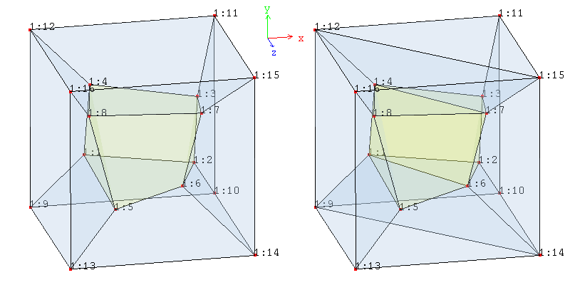
Patch geometry for hexahedral elements only (left) and prismatic/hexahedral elements (right)
A linear displacement is enforced on the outer surface of the patch, which consists of an isotropic elastic material. The corresponding analytical strain state is that of a constant strain.
The following conditions are verified to be within the machine’s numerical tolerance (typically 1e-13):
The displacements at all (interior and exterior) nodes must fit the imposed displacement field.
At all integration points, the strain tensor must be equal to the analytically determined constant strain.
At all integration points, the stress tensor must be equal to the analytically determined constant stress.
The node coordinates, displacement field, and material properties are the following:
Node |
X |
Y |
Z |
|
1 |
0.249 |
0.342 |
0.192 |
|
2 |
0.826 |
0.288 |
0.288 |
|
3 |
0.850 |
0.649 |
0.263 |
|
4 |
0.273 |
0.750 |
0.230 |
|
5 |
0.320 |
0.186 |
0.643 |
|
6 |
0.677 |
0.305 |
0.683 |
|
7 |
0.788 |
0.693 |
0.644 |
|
8 |
0.165 |
0.745 |
0.702 |
|
9 |
0.0 |
0.0 |
0.0 |
|
10 |
1.0 |
0.0 |
0.0 |
|
11 |
1.0 |
1.0 |
0.0 |
|
12 |
0.0 |
1.0 |
0.0 |
|
13 |
0.0 |
0.0 |
1.0 |
|
14 |
1.0 |
0.0 |
1.0 |
|
15 |
1.0 |
1.0 |
1.0 |
|
16 |
0.0 |
1.0 |
1.0 |
E |
1e6 |
nu |
0.25 |
X |
0.0005 * (2x + y + z) |
Y |
0.0005 * (x + 2y + z) |
Z |
0.0005 * (x + y + 2z) |
Exx |
0.001 |
Eyy |
0.001 |
Ezz |
0.001 |
Exy |
0.0005 |
Eyz |
0.0005 |
Exz |
0.0005 |
Sxx |
2000 |
Syy |
2000 |
Szz |
2000 |
Sxy |
400 |
Syz |
400 |
Sxz |
400 |
6.11.4. Solid Element Strain and Stress Tests
Folder: $B2VERIFICATION/basic/sild/case5
This test is based on Bathe [bathe1996] (example 6.6 in later editions of his text book). It tests the linear and non-linear stress computation of 8-node volume elements. Strains and stresses are compared to the analytical solution for the linear case. For the nonlinear case, the Green-Lagrange strains and the Cauchy stresses are separately computed by the test and compared to the strains and stresses obtained from the FE analysis.
6.11.5. Solid HE Elements Pressure Loads
Folder: $B2VERIFICATION/basic/solids/cylinder
Perform a linear deformation and stress analysis of a thin cylinder under an inner pressure of 1 MPa. The cylinder can expand freely. Since the analysis is linear and only external forces are applied, we can define 2 subcases of a single case (case 1):
Case 1, subcase 1: Normal pressure applied on inner wall.
Case 1, subcase 2: Surface traction applied on inner wall. Tractions orientation is *local. Subcase 2 is equivalent to subcase 1.
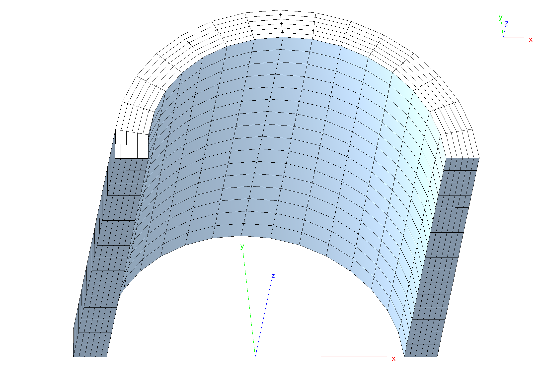
Cylinder mesh (half cylinder modeled).
Subcase 1 defines (normal) pressure loads by generating these on selected element faces by means of the nbc command:
nbc 1 type pressure
   title 'Pressure on inner wall'
   pressure (p)
   epatch 1 f4 # Apply normal pressure p to face 4 of epatch 1
end
Subcase 2 generates normal pressure loads with surface tractions oriented i n the element face local system, see nbc:
nbc 2 domain=eface type surface_tractions system local
   title 'Pressure on inner wall defined with surface tractions'
   surface_tractions 0 0 (-p)
   epatch 1 f4 # Apply traction p in local z-direction to face 4 of epatch 1
end
The baspl++ script bv-stress.py plots the (constant) hoop stress (50 Mpa).
6.12. Spring Element Tests
Note
Location of verification case:
verification/basic/spring
These tests check the correct functioning of the string element.
6.13. Basic Thermal Stress Tests
6.13.1. One-element linear thermal stress tests
Folder: B2VERIFICATION/basic/thermalstresses
The one element test checks linear deformations, strains, stresses, and reaction force produced by the element against the analytical solutions. For a homogeneous free body the analytical solutions for the strains are given by
εii= αiΔT
αi being the thermal dilatation coefficient in the i-direction. The total deformation di in the i-direction is then, with Li being the length of the element in the i-direction:
dx= εxxLx
For a homogeneous constrained body the stresses are
σii= E εii
6.13.2. Beam linear thermal stress tests
Note
Location of verification case:
verification/basic/thermalstresses
A clamped beam with rectangular section is subject to a uniform and a differential temperature. For the uniform temperature case the analytical solution for the stress is given by σ11= α1ΔT E in the beam direction (constant stress) and the beam does not deform. For the differential temperature case the analytical solution for the maximum bending stress is given by σ11= α1ΔT E I / t, where E is the modulus of elasticity , I the moment of inertia around the beam y-axis, and t the beam thickness.